Maintenance
5-1
October 2007
Minor Maintenance of
Sensor Optics
Periodically inspect and maintain the sensor optics as described in the
following chapter. These procedures can be performed at any time,
but are only necessary when the
Service
indicator appears on the
status display, indicating that service is required.
Cleaning and Balancing
the Sensor Mirror
Under normal conditions, the system is self-checking and self-
balancing. However, there are occasions when particulate matter and
water-soluble contaminants reduce sensor mirror reflectance and
system accuracy (see
Contamination
on page 3-6). Three features of
the OptiSonde system allow users to monitor and adjust the mirror:
•
The balance indicator (shown in Figure 5-1 below) provides a
graphic display of how much light is received by the mirror’s
photodetector. It is also an indicator of the dew layer thickness.
This indicator increases and decreases in digital steps.
•
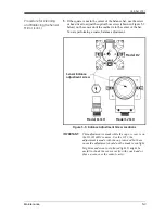
The bias screw adjusts the light signal received by the reference
photodetector and is used as a “coarse adjustment.”
•
The automatic balance, or PACER cycle (discussed on page 1-6),
electronically fine tunes the optical balance between the IR
emitters and reference photodetectors.
In operation, the position of the balance indicator will depend on the
level of humidity and the sensor used. As the humidity changes, the
chilled mirror system will seek to establish control.
As contaminants deposit on the mirror, the balance indicator will
increase, as will the dew point readings. The
PACER
cycle or manual
cleaning and balancing (followed by the
PACER
cycle) will mitigate
the contamination.
Note:
If the mirror is severely scratched or pitted, you may not be
able to balance it. It may be replaced in the field, as discussed
on page 5-5. For industrial applications, GE Sensing
recommends the solid platinum mirror.
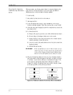
Figure 5-1: Balance and Status Indicator on OptiSonde Display
Balance
Indicator
Status
Indicator
Menu: x Auto Cycle
e
mbar
6.0179
T
a
°C
+25.09
14:33
Summary of Contents for 1111H
Page 1: ...GE Sensing OptiSonde General Eastern Chilled Mirror Hygrometer User s Manual ...
Page 9: ...Chapter 1 ...
Page 15: ...Chapter 2 ...
Page 33: ...Chapter 3 ...
Page 43: ...Chapter 4 ...
Page 57: ...Chapter 5 ...
Page 68: ...Appendix A ...
Page 73: ...Appendix B ...
Page 74: ...Humidity Equations and Conversion Chart Introduction B 1 Vapor Pressure B 1 Humidity B 2 ...
Page 78: ...Appendix C ...
Page 79: ...Configuring the Serial Interface Wiring to a Personal Computer C 1 ...
Page 82: ...Appendix D ...
Page 87: ...Appendix E ...
Page 88: ...Theory of Operation and Glossary Theory of Operation E 1 The PACER Cycle E 4 Glossary E 5 ...


