Configuring the Serial Interface
C-1
October 2007
Wiring to a Personal
Computer
The OptiSonde is configured as Data Terminal Equipment (DTE).
The following pins are used in the serial interface:
•
2 - Transmitted data (
TXD
)
•
3 - Received data (
RXD
)
•
5 - Signal ground (
GND
)
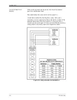
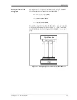
To send the output of a benchtop OptiSonde to a personal computer,
use the cable arrangement shown in Figure C-1 below. For a wall-
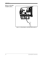
mount OptiSonde, use the wiring shown in Figure C-2 on the next
page.
Figure C-1: Wiring Diagram - Benchtop OptiSonde to PC
OptiSonde
PC
9-Pin Female
9-Pin
3
2
5
3
2
5
(TX)
(RX)
(GND)
Summary of Contents for 1111H
Page 1: ...GE Sensing OptiSonde General Eastern Chilled Mirror Hygrometer User s Manual ...
Page 9: ...Chapter 1 ...
Page 15: ...Chapter 2 ...
Page 33: ...Chapter 3 ...
Page 43: ...Chapter 4 ...
Page 57: ...Chapter 5 ...
Page 68: ...Appendix A ...
Page 73: ...Appendix B ...
Page 74: ...Humidity Equations and Conversion Chart Introduction B 1 Vapor Pressure B 1 Humidity B 2 ...
Page 78: ...Appendix C ...
Page 79: ...Configuring the Serial Interface Wiring to a Personal Computer C 1 ...
Page 82: ...Appendix D ...
Page 87: ...Appendix E ...
Page 88: ...Theory of Operation and Glossary Theory of Operation E 1 The PACER Cycle E 4 Glossary E 5 ...

