October 2007
2-10
Installation
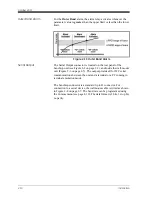
Outer Band Alarm
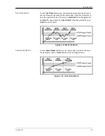
For the
Outer Band
alarm, the alarm relay activates whenever the
parameter value is
greater
than the upper limit or less than the lower
limit.
Figure 2-11: Outer Band Alarm
Serial Output
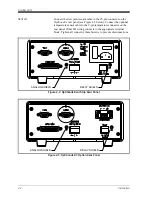
The Serial Output connector is located on the rear panel of the
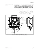
benchtop unit (see Figure 2-2 on page 2-2), and inside the wall-mount
unit (Figure 2-6 on page 2-5). The output provides RS-232C serial
communications between the unit and a terminal or a PC running in
terminal emulation mode.
The benchtop connector is a standard 9-pin D connector. For
connection to a serial device, the wallmount cable is wired as shown
in Figure 2-8 on page 2-7. The baud rate can be programmed using
the Comms menu (see page 4-10). The data format is 8 bits, 1 stop bit,
no parity.
Summary of Contents for 1111H
Page 1: ...GE Sensing OptiSonde General Eastern Chilled Mirror Hygrometer User s Manual ...
Page 9: ...Chapter 1 ...
Page 15: ...Chapter 2 ...
Page 33: ...Chapter 3 ...
Page 43: ...Chapter 4 ...
Page 57: ...Chapter 5 ...
Page 68: ...Appendix A ...
Page 73: ...Appendix B ...
Page 74: ...Humidity Equations and Conversion Chart Introduction B 1 Vapor Pressure B 1 Humidity B 2 ...
Page 78: ...Appendix C ...
Page 79: ...Configuring the Serial Interface Wiring to a Personal Computer C 1 ...
Page 82: ...Appendix D ...
Page 87: ...Appendix E ...
Page 88: ...Theory of Operation and Glossary Theory of Operation E 1 The PACER Cycle E 4 Glossary E 5 ...

