October 2007
3-2
Operation
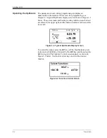
Operating the OptiSonde
The parameters chosen during programming are displayed
numerically in the middle of the screen. For programming, see
Chapter 4. A typical OptiSonde display screen is shown in Figure 3-1
below. The system status and heating/cooling indicator (small arrow)
are shown in the upper right, and the balance indicator is shown in the
lower left.
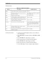
Figure 3-1: Typical OptiSonde Display Screen
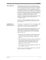
To control the sensor, press the
ENT
key. (If the OptiSonde keys are
locked, press the
ESC
key, followed by the
ENT
key, and then press the
ESC
key again.) The Function Control screen appears, as shown in
Figure 3-2 below. Use the four arrow keys to select the desired
function
Figure 3-2: Function Control Screen
Menu: x Auto Cycle
e
mbar
6.0179
T
a
°C
+25.09
14:33
Select Function:
_
PACER AUTO
`
HEAT
COOL
Summary of Contents for 1111H
Page 1: ...GE Sensing OptiSonde General Eastern Chilled Mirror Hygrometer User s Manual ...
Page 9: ...Chapter 1 ...
Page 15: ...Chapter 2 ...
Page 33: ...Chapter 3 ...
Page 43: ...Chapter 4 ...
Page 57: ...Chapter 5 ...
Page 68: ...Appendix A ...
Page 73: ...Appendix B ...
Page 74: ...Humidity Equations and Conversion Chart Introduction B 1 Vapor Pressure B 1 Humidity B 2 ...
Page 78: ...Appendix C ...
Page 79: ...Configuring the Serial Interface Wiring to a Personal Computer C 1 ...
Page 82: ...Appendix D ...
Page 87: ...Appendix E ...
Page 88: ...Theory of Operation and Glossary Theory of Operation E 1 The PACER Cycle E 4 Glossary E 5 ...


