Maintenance
5-7
October 2007
Test and Calibration
The procedures in this section effectively test and/or calibrate the
following aspects of the OptiSonde:
•
Startup and power supply voltage
•
Normal sensor operation
•
Front panel display
•
Digital and analog outputs.
The unit has been completely tested and calibrated at the factory, and
is ready to plug in and operate. As shipped, it meets all of our
published specifications.
When ordered as a complete hygrometer system with a chilled mirror
sensor and cable, it is verified at a number of points against a dew
point system that has been certified by the U.S. National Institute of
Standards and Technology (NIST). A Certificate of Compliance is
supplied with the unit to indicate traceability.
Troubleshooting
The Display Doesn’t Light
Up
1.
On the benchtop model, check the
POWER
switch on the rear
panel. Make sure it’s
ON
.
2.
Check the line cord. Make sure both ends are plugged in and that it
is plugged into a proper source of AC voltage.
3.
Check the power supply. Make sure it is connected and has the
proper output voltage.
4.
Check the fuse. Make sure the proper fuse size is installed. Make
sure the fuse is not open.
“Service” Appears on the
STATUS Display Line
The text “
Service Req
” displayed on the
STATUS
line means service
is required. The most frequent problem requiring service is that the
mirror surface is contaminated and should be cleaned.
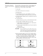
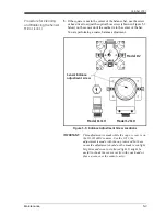
Clean and balance the sensor mirror (refer to
Minor Maintenance of
Sensor Optics
on page 5-1). Next, run the instrument through a
PACER cycle. If, at the end of the cycle, the
Service Req
status
appears again, repeat the cleaning and balancing procedure, or contact
the factory.
Summary of Contents for 1111H
Page 1: ...GE Sensing OptiSonde General Eastern Chilled Mirror Hygrometer User s Manual ...
Page 9: ...Chapter 1 ...
Page 15: ...Chapter 2 ...
Page 33: ...Chapter 3 ...
Page 43: ...Chapter 4 ...
Page 57: ...Chapter 5 ...
Page 68: ...Appendix A ...
Page 73: ...Appendix B ...
Page 74: ...Humidity Equations and Conversion Chart Introduction B 1 Vapor Pressure B 1 Humidity B 2 ...
Page 78: ...Appendix C ...
Page 79: ...Configuring the Serial Interface Wiring to a Personal Computer C 1 ...
Page 82: ...Appendix D ...
Page 87: ...Appendix E ...
Page 88: ...Theory of Operation and Glossary Theory of Operation E 1 The PACER Cycle E 4 Glossary E 5 ...


