Index
3
October 2007
Index (cont.)
S
Sample Line Maintenance . . . . . . . . . . . . . . . 3-8
Sampling Lines. . . . . . . . . . . . . . . . . . 2-12, 2-13
Scaling, Definition . . . . . . . . . . . . . . . . . . . . . E-5
Sensor Mirror, Cleaning and Balancing . . . . . 5-1
Sensors . . . . . . . . . . . . . . . . . . . . . . . . . . . . . . 1-4
Balancing . . . . . . . . . . . . . . . . . . . . . . . . . . 3-5
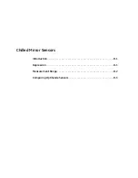
Chilled Mirror . . . . . . . . . . . . . . . . . . . . . .D-1
Cleaning the Mirror . . . . . . . . . . . . . . . . . . 5-1
Comparison Chart . . . . . . . . . . . . . . . . . . .D-3
Connecting . . . . . . . . . . . . . . . . . . . . . . . . 2-16
Dew Point. . . . . . . . . . . . . . . . . . . . . . . . . . 1-4
Heat Transfer . . . . . . . . . . . . . . . . . . . . . . 2-12
Information. . . . . . . . . . . . . . . . . . . . . . . . 2-11
Installation . . . . . . . . . . . . . . . . . . . 2-11, 2-14
Maintenance . . . . . . . . . . . . . . . . . . . . 5-1, 5-5
Model 1111H . . . . . . . . . . . . . . . . . . . . . . 2-14
Model 1211H . . . . . . . . . . . . . . . . . . . . . . 2-15
Model D-2 . . . . . . . . . . . . . . . . . . . . . . . . 2-15
Pressure . . . . . . . . . . . . . . . . . . . . . . . . . . . 1-4
Replacing Mirrors . . . . . . . . . . . . . . . . . . . 5-5
Temperature . . . . . . . . . . . . . . . . . . . . . . . . 1-4
Serial Outputs
Troubleshooting . . . . . . . . . . . . . . . . . . . . . 5-9
Wiring. . . . . . . . . . . . . . . . . . . . . . . . . . . . 2-10
Service Required . . . . . . . . . . . . . . . . . . . . . . 5-7
Set Point Alarm . . . . . . . . . . . . . . . . . . . . . . . 2-9
Specifications
Functional. . . . . . . . . . . . . . . . . . . . . . . . . .A-2
Optional Accessories . . . . . . . . . . . . . . . . .A-3
Performance . . . . . . . . . . . . . . . . . . . . . . . .A-1
Physical (Benchtop) . . . . . . . . . . . . . . . . . .A-3
Physical (Wall-Mount) . . . . . . . . . . . . . . . .A-3
Status Line Indications . . . . . . . . . . . . . . . . . . 3-3
Supercooled Dew Points . . . . . . . . . . . . . . . . 3-6
System
Components . . . . . . . . . . . . . . . . . . . . . . . . 1-3
T
Testing. . . . . . . . . . . . . . . . . . . . . . . . . . . . . . .5-7
Troubleshooting . . . . . . . . . . . . . . . . . . . . . . .5-7
"Balance" on Display . . . . . . . . . . . . . . . . .5-9
"Service" Required . . . . . . . . . . . . . . . . . . .5-7
Incorrect Dew Point Display. . . . . . . . . . . .5-8
No Analog Output. . . . . . . . . . . . . . . . . . . .5-9
No Display . . . . . . . . . . . . . . . . . . . . . . . . .5-7
No Serial Output . . . . . . . . . . . . . . . . . . . . .5-9
V
Vapor Pressure . . . . . . . . . . . . . . . . . . . . . . . B-1
W
Wall-Mount
Installation. . . . . . . . . . . . . . . . . . . . . . . . . .2-3
Specifications . . . . . . . . . . . . . . . . . . . . . . A-3
Wiring Input Power. . . . . . . . . . . . . . . . . . .2-6
Wiring Outputs . . . . . . . . . . . . . . . . . . . . . .2-7
Water-Soluble Contaminants . . . . . . . . . . . . .3-7
Wiring
Alarm Outputs. . . . . . . . . . . . . . . . . . . . . . .2-8
Analog Outputs . . . . . . . . . . . . . . . . . . . . . .2-8
Outputs . . . . . . . . . . . . . . . . . . . . . . . . . . . .2-7
Serial Output . . . . . . . . . . . . . . . . . . . . . . .2-10
Wall-Mount . . . . . . . . . . . . . . . . . . . . . . . . .2-4
Summary of Contents for 1111H
Page 1: ...GE Sensing OptiSonde General Eastern Chilled Mirror Hygrometer User s Manual ...
Page 9: ...Chapter 1 ...
Page 15: ...Chapter 2 ...
Page 33: ...Chapter 3 ...
Page 43: ...Chapter 4 ...
Page 57: ...Chapter 5 ...
Page 68: ...Appendix A ...
Page 73: ...Appendix B ...
Page 74: ...Humidity Equations and Conversion Chart Introduction B 1 Vapor Pressure B 1 Humidity B 2 ...
Page 78: ...Appendix C ...
Page 79: ...Configuring the Serial Interface Wiring to a Personal Computer C 1 ...
Page 82: ...Appendix D ...
Page 87: ...Appendix E ...
Page 88: ...Theory of Operation and Glossary Theory of Operation E 1 The PACER Cycle E 4 Glossary E 5 ...


