2 INSTALLATION
g
GE Power Management
16
2.6 Ground Fault CT
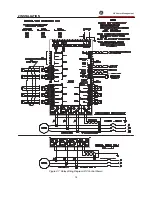
All current carrying conductors must pass through a separate ground fault CT in order for the ground fault function to
operate correctly. If a safety ground is used it should pass outside the CT window.
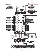
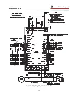
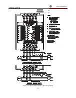
The ground fault CT is connected to terminals 73 and 72 for 5 amp secondary CTs or to terminals 73 and 74 for
Multilin 2000:1 CTs. as shown in Figures 2-4, 2-6, 2-7. The polarity of the ground fault CT connection is not
important. It is recommended that the two CT leads be twisted together to minimize noise pickup. If a 2000:1 ground
fault CT is used, the secondary output will be a low level signal which allows for sensitive ground fault detection.
The zero sequence ground fault connection is recommended. If the residual ground fault method is used the 169
relay will not display ground fault current in direct primary amps.
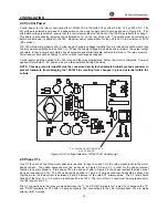
The connections to the 169 internal ground fault CT are made directly via #10 screws.
2.7 Trip Relay Contacts
The main control relay or shunt trip coil of the motor starter or circuit breaker should be connected to the Trip relay
contacts of the 169. These contacts are available as normally open (NO), normally closed (NC), and can switch up
to 10 amps at either 250 VAC or 30 VDC with a resistive load. Silver cadmium oxide contacts are used because of
their ability to handle high inrush currents on inductive loads. Contact Multilin if these contacts are to be used for
carrying low currents since they are not recommended for use below 0.1 amps. Connection to the motor contactor
or breaker is shown in Figures 2-4, 2-6, 2-7.
The Trip output relay will remain latched after a trip. This means that once this relay has been activated it will remain
in the active state until the 169 is manually reset. The Trip relay contacts may be reset by pressing the RESET key
(see section 3.1) if motor conditions allow, or by using the Emergency Restart feature (see section 2.12). An
optional single shot restart can be selected on the 169 Plus to automatically reset the relay after a running
OVERLOAD TRIP. This feature is selected or defeated in page 5 of SETPOINTS mode.
The Trip relay may be programmed to be fail-safe or non-fail-safe. When in the fail-safe mode, relay activation or a
loss of power condition will cause the relay contacts to go to their power down state. Thus, in order to cause a trip
on loss of power to the 169, output relays should be programmed as fail-safe.
The Trip relay cannot be reset if a lock-out is in effect. Lock-out time will be adhered to regardless of whether control
power is present or not.
The Trip relay can be programmed to activate on any combination of the following trip conditions: overload, stator
RTD overtemperature, rapid trip, unbalance, ground fault, short circuit, RTD overtemperature, phase reversal,
acceleration time, number of starts per hour, single phase, speed switch closure on start, differential relay closure,
spare input closure, and start inhibit (see section 3.4 for factory preset configurations). Connections to the Trip relay
contacts are made via a terminal block which uses #6 screws.
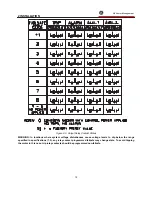
NOTE: The rear of the 169 relay shows output relay contacts in their power down state. Figures 2-4, 2-6, 2-7
show output relay contacts with power applied, no trips or alarms, and Factory Configurations in effect (i.e.
TRIP - fail-safe, ALARM - non-fail-safe, AUX.1 - non-fail-safe, AUX.2 - fail-safe). See Figure 2-5 for a list of all
possible contact states.
2.8 Alarm Relay Contacts
These contacts are available as normally open (NO), normally closed (NC), with the same ratings as the Trip relay
but can only be programmed to activate when alarm setpoint levels are reached. (On a Draw-out version of 169,
only one set of alarm contacts is available and the user must specify normally open or normally closed when
ordering). Thus these contacts may be used to signal a low level fault condition prior to motor shut-down.
Conditions which can be programmed to activate the relay are alarm levels for the following functions: immediate
overload, unbalance, undercurrent, ground fault, stator RTD overtemperature, RTD overtemperature, broken RTD
sensor, spare input alarm, self-test alarm, and start inhibit (see section 3.4 for factory preset configurations). The
relay can be configured as latched or unlatched and fail-safe or non-fail-safe. Connections to the Alarm relay
contacts are made via a terminal block which uses #6 screws.
NOTE: The rear of the 169 relay shows output relay contacts in their power down state. Figures 2-4, 2-6, 2-7 show
output relay contacts with power applied, no trips or alarms, and Factory Configurations in effect (i.e. TRIP - fail-safe,
ALARM - non-fail-safe, AUX.1 - non-fail-safe, AUX.2 - fail-safe). See Figure 2-5 for a list of all possible contact
states.
Summary of Contents for 169
Page 12: ......
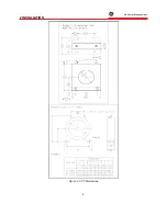
Page 14: ...2 INSTALLATION g GE Power Management 8 Figure 2 2 CT Dimensions ...
Page 17: ...2 INSTALLATION g GE Power Management 11 Figure 2 4 Relay Wiring Diagram AC control power ...
Page 19: ...2 INSTALLATION g GE Power Management 13 Figure 2 6 Relay Wiring Diagram Two Phase CTs ...
Page 20: ...2 INSTALLATION g GE Power Management 14 Figure 2 7 Relay Wiring Diagram DC Control Power ...
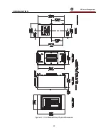
Page 28: ...2 INSTALLATION g GE Power Management 22 Figure 2 10 169 Drawout Relay Physical Dimensions ...
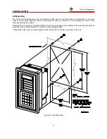
Page 29: ...2 INSTALLATION g GE Power Management 23 Figure 2 11 169 Drawout Relay Mounting ...
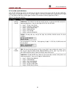
Page 31: ...3 SETUP AND USE g GE Power Management 25 Figure 3 1 Front Panel Controls and Indicators ...
Page 73: ...3 SETUP AND USE g GE Power Management 67 Figure 3 2 Standard Overload Curves ...
Page 74: ...3 SETUP AND USE g GE Power Management 68 A B Figure 3 3 Custom Curve Examples ...
Page 88: ...5 THEORY OF OPERATION g GE Power Management 82 Figure 5 1 Hardware Block Diagram ...
Page 90: ...5 THEORY OF OPERATION g GE Power Management 84 Figure 5 2 Firmware Block Diagram ...

