2 INSTALLATION
g
GE Power Management
17
2.9 Auxiliary Relay #1 Contacts (169 Plus)
Auxiliary relay #1 is provided to give an extra set of NO/NC contacts which operate independently of the other relay
contacts. (On a Draw-out version of 169, only one set of Aux.1 contacts is available and the user must specify
normally open or normally closed when ordering). This auxiliary relay has the same ratings as the Trip relay.
Auxiliary relay #1 can be configured as latched or unlatched and fail-safe or non-fail-safe. The conditions that will
activate this relay can be any trip or alarm indications (see section 3.4 for factory preset configurations).
These contacts may be used for alarm purposes or to trip devices other than the motor contactor. For example, the
ground fault and short circuit functions may be directed to Auxiliary relay #1 to trip the main circuit breaker rather
than the motor starter.
Connections to the relay contacts are made via a terminal block which uses #6 screws.
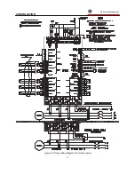
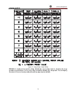
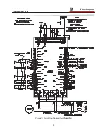
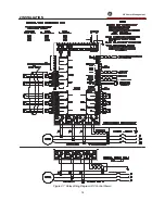
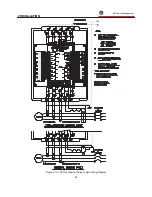
NOTE: The rear of the 169 relay shows output relay contacts in their power down state. Figures 2-4, 2-6, 2-7
show output relay contacts with power applied, no trips or alarms, and Factory Configurations in effect (i.e.
TRIP - fail-safe, ALARM - non-fail-safe, AUX.1 - non-fail-safe, AUX.2 - fail-safe). See Figure 2-5 for a list of all
possible contact states.
2.10 Auxiliary Relay #2 Contacts (169 Plus)
This relay provides another set of NO/NC contacts with the same ratings as the other relays. (On a Draw-out version
of 169, only one set of Aux.2 contacts is available and the user must specify normally open or normally closed when
ordering). This relay is different from the others in the fact that it is permanently programmed as latched and fail-
safe.
This relay may be programmed to activate on any combination of alarm conditions (see section 3.4 for factory preset
configurations). The feature assignment programming is thus the same as for the Alarm relay.
Connections to the relay contacts are made via a terminal block which uses #6 screws.
NOTE: The rear of the 169 relay shows output relay contacts in their power down state. Figures 2-4, 2-6, 2-7
show output relay contacts with power applied, no trips or alarms, and Factory Configurations in effect (i.e.
TRIP - fail-safe, ALARM - non-fail-safe, AUX.1 - non-fail-safe, AUX.2 - fail-safe). See Figure 2-5 for a list of all
possible contact states.
2.11 RTD Sensor Connections
Up to six resistance temperature detectors (RTDs) may be used for motor stator temperature monitoring. The
remaining RTD inputs may be used for motor and load bearing, or other temperature monitoring functions. All RTDs
must be of the same type. RTD #8 (RTD #10 on the 169 Plus) may be used to monitor ambient air temperature.
This is done to enhance protection in environments where the ambient temperature varies considerably. Use of
stator RTDs will allow the 169 to "learn" the actual cooling times of the motor. When no stator RTDs are used the
169 will not learn the actual motor cooling times, but will rely on the user defined preset values. The number of
stator RTDs used together with RTD trip and alarm temperatures must be programmed into the 169 (see sections
3.16, 3.17). The RTD type to be used must be specified when ordering the 169 relay. If the type of RTD in use is to
be changed, the 169 must be returned to the factory.
Each RTD has four connections to the 169 relay as shown in Figures 2-4, 2-6, 2-7. Since the RTD indicates
temperature by the value of its resistance, it is necessary to compensate for the resistance of the connecting wires,
which is dependent on lead length and ambient temperature. The 169 uses a circuit to cancel this resistance and
read only the actual RTD resistance. Correct operation will occur providing all three wires are of the same length and
the lead resistance is not greater than 25% of the RTD 0 C resistance. This can be accomplished by using identical
lengths of the same type of wire. If 10 copper RTDs are to be used special care should be taken to keep the lead
resistance as low as possible.
If RTD #8 (RTD #10 on the 169 Plus) is to be used for ambient air temperature measurement the RTD should be
placed and mounted somewhere in the motor cooling air intake flow. The sensor should be in direct contact with the
cooling air but not with any surface that is at a temperature other than the cooling air. This RTD is selected for
ambient temperature use in page 5 of SETPOINTS mode.
If no RTD sensor is to be connected to any of the RTD terminals on the 169, the terminals may be left open.
If fewer than 6 stator RTDs are to be employed, they should be connected to the lowest numbered relay RTD
connections. For example, if 3 stator RTDs are to be used they should be connected to the terminals for RTD1,
Summary of Contents for 169
Page 12: ......
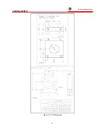
Page 14: ...2 INSTALLATION g GE Power Management 8 Figure 2 2 CT Dimensions ...
Page 17: ...2 INSTALLATION g GE Power Management 11 Figure 2 4 Relay Wiring Diagram AC control power ...
Page 19: ...2 INSTALLATION g GE Power Management 13 Figure 2 6 Relay Wiring Diagram Two Phase CTs ...
Page 20: ...2 INSTALLATION g GE Power Management 14 Figure 2 7 Relay Wiring Diagram DC Control Power ...
Page 28: ...2 INSTALLATION g GE Power Management 22 Figure 2 10 169 Drawout Relay Physical Dimensions ...
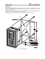
Page 29: ...2 INSTALLATION g GE Power Management 23 Figure 2 11 169 Drawout Relay Mounting ...
Page 31: ...3 SETUP AND USE g GE Power Management 25 Figure 3 1 Front Panel Controls and Indicators ...
Page 73: ...3 SETUP AND USE g GE Power Management 67 Figure 3 2 Standard Overload Curves ...
Page 74: ...3 SETUP AND USE g GE Power Management 68 A B Figure 3 3 Custom Curve Examples ...
Page 88: ...5 THEORY OF OPERATION g GE Power Management 82 Figure 5 1 Hardware Block Diagram ...
Page 90: ...5 THEORY OF OPERATION g GE Power Management 84 Figure 5 2 Firmware Block Diagram ...

