3 SETUP AND USE
g
GE Power Management
28
No.
Name
Description
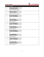
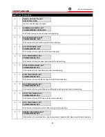
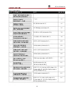
EFFECT: Pressing the LINE DOWN key will cause the display to show the next line of the
currently selected page of information. Pressing the LINE UP key will cause the display to
show the line immediately in front of the currently displayed line.
USE: These keys can be used at any time in any relay mode of operation. If the display
shows the last line of a page the LINE DOWN key will have no effect. If the display shows
the first line of a page the LINE UP key will have no effect.
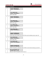
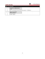
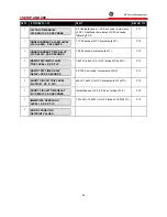
FUNCTION: The VALUE UP and VALUE DOWN keys allow the user to alter the currently
selected setpoint. If either key is held for more than 1/2 second the setpoint selected will
increment or decrement at a fast rate. If either key is held for more than 2 seconds the
setpoint selected will increment or decrement at a very fast rate.
EFFECT: Pressing the VALUE UP key will cause the currently displayed setpoint value to
increment. Pressing the VALUE DOWN key will cause the currently displayed setpoint
value to decrement. For YES/NO questions, pressing either key will cause the answer to
change. Any changed setpoint will not be used internally until the STORE key is pressed.
8,9
VALUE
UP
VALUE
DOWN
USE: These keys can be pressed any time a setpoint is displayed in SETPOINTS mode or
when a YES/NO question is displayed in ACTUAL VALUES mode (see STORE key). When
the desired setpoint value is reached the STORE key is used to save it. If an altered
setpoint is not stored the previous value will still be in effect.
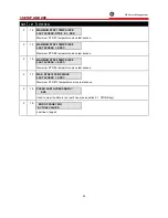
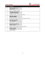
FUNCTION: The RESET key allows the user to reset the 169 after any of the latched
output relays have become active so that a motor start can be attempted.
EFFECT: Pressing this key will reset (i.e. return to an inactive state) any of the active
output relay contacts if motor conditions allow (see below). The message,
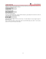
RESET NOT POSSIBLE -
Condition still present
will be displayed if any active output relays cannot be reset
10
RESET
USE: A latched relay cannot be reset if the trip/alarm condition persists (e.g. an
OVERLOAD TRIP lock-out or a high RTD temperature). Pre-trip motor values may be
viewed in ACTUAL VALUES mode page 5 (Pre-trip Data). If an immediate restart is
required after an OVERLOAD or STARTS/HOUR TRIP the Emergency Restart terminals
(see section 2.12) may be shorted together. This will reduce the lock-out time to 0 minutes.
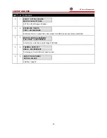
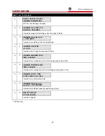
FUNCTION: In SETPOINTS mode the CLEAR key allows the user to return an altered,
non-stored setpoint to its original value. In HELP mode the CLEAR key allows the user to
return to the previous display mode.
EFFECT: When this key is pressed in SETPOINTS mode any altered, currently displayed
setpoint will be returned to its original value. When this key is pressed in HELP mode the
relay will return to the line and page of the mode active when the HELP key was pressed.
11
CLEAR
USE: This key can be used in SETPOINTS or HELP modes only. In SETPOINTS mode it
can only be used when a displayed setpoint has been changed with the VALUE UP/VALUE
DOWN keys but has not yet been stored. After a setpoint has been stored the CLEAR key
will have no effect. In HELP mode the CLEAR key can be used any time there is a HELP
message on the display.
Summary of Contents for 169
Page 12: ......
Page 14: ...2 INSTALLATION g GE Power Management 8 Figure 2 2 CT Dimensions ...
Page 17: ...2 INSTALLATION g GE Power Management 11 Figure 2 4 Relay Wiring Diagram AC control power ...
Page 19: ...2 INSTALLATION g GE Power Management 13 Figure 2 6 Relay Wiring Diagram Two Phase CTs ...
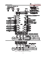
Page 20: ...2 INSTALLATION g GE Power Management 14 Figure 2 7 Relay Wiring Diagram DC Control Power ...
Page 28: ...2 INSTALLATION g GE Power Management 22 Figure 2 10 169 Drawout Relay Physical Dimensions ...
Page 29: ...2 INSTALLATION g GE Power Management 23 Figure 2 11 169 Drawout Relay Mounting ...
Page 31: ...3 SETUP AND USE g GE Power Management 25 Figure 3 1 Front Panel Controls and Indicators ...
Page 73: ...3 SETUP AND USE g GE Power Management 67 Figure 3 2 Standard Overload Curves ...
Page 74: ...3 SETUP AND USE g GE Power Management 68 A B Figure 3 3 Custom Curve Examples ...
Page 88: ...5 THEORY OF OPERATION g GE Power Management 82 Figure 5 1 Hardware Block Diagram ...
Page 90: ...5 THEORY OF OPERATION g GE Power Management 84 Figure 5 2 Firmware Block Diagram ...

