3 SETUP AND USE
g
GE Power Management
40
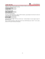
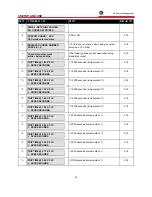
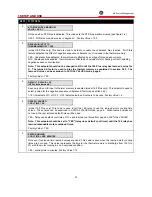
To place the relay in ACTUAL VALUES mode, the ACTUAL VALUES key must be pressed. When this is done the
following flash message will appear for 2 seconds,
ACTUAL VALUES HAS SIX
PAGES OF DATA
The display will then show,
PAGE 1: ACTUAL VALUES
PHASE CURRENT DATA
which is the beginning of page 1.
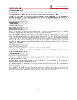
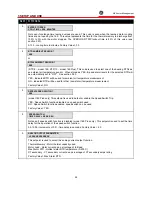
If the relay is in SETPOINTS mode or ACTUAL VALUES mode and no key is pressed for more than four minutes the
display will change to, (factory default settings)
I1= XXX I2= XXX
I3= XXX (AMPS) ---
which is the third line in page 1 of ACTUAL VALUES mode. This default display line can be changed in page 5 of
SETPOINTS mode.
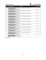
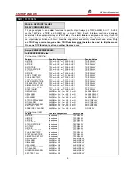
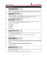
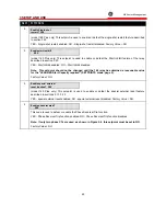
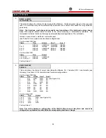
When in this mode the PAGE UP, PAGE DOWN, LINE UP, and LINE DOWN keys (see section 3.1) can be used to
examine all of the actual motor data outlined above.
Summary of Contents for 169
Page 12: ......
Page 14: ...2 INSTALLATION g GE Power Management 8 Figure 2 2 CT Dimensions ...
Page 17: ...2 INSTALLATION g GE Power Management 11 Figure 2 4 Relay Wiring Diagram AC control power ...
Page 19: ...2 INSTALLATION g GE Power Management 13 Figure 2 6 Relay Wiring Diagram Two Phase CTs ...
Page 20: ...2 INSTALLATION g GE Power Management 14 Figure 2 7 Relay Wiring Diagram DC Control Power ...
Page 28: ...2 INSTALLATION g GE Power Management 22 Figure 2 10 169 Drawout Relay Physical Dimensions ...
Page 29: ...2 INSTALLATION g GE Power Management 23 Figure 2 11 169 Drawout Relay Mounting ...
Page 31: ...3 SETUP AND USE g GE Power Management 25 Figure 3 1 Front Panel Controls and Indicators ...
Page 73: ...3 SETUP AND USE g GE Power Management 67 Figure 3 2 Standard Overload Curves ...
Page 74: ...3 SETUP AND USE g GE Power Management 68 A B Figure 3 3 Custom Curve Examples ...
Page 88: ...5 THEORY OF OPERATION g GE Power Management 82 Figure 5 1 Hardware Block Diagram ...
Page 90: ...5 THEORY OF OPERATION g GE Power Management 84 Figure 5 2 Firmware Block Diagram ...

