3 SETUP AND USE
g
GE Power Management
42
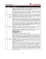
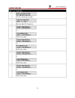
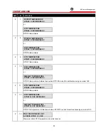
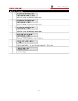
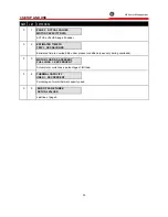
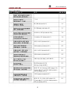
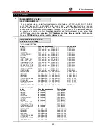
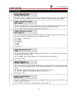
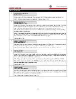
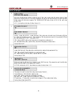
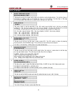
Table 3-3 SETPOINTS
3$*(
,1)250$7,21 /,1(
5$1*(
0$18$/ 5()
1
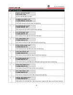
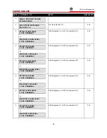
PAGE 1: SETPOINTS VALUES
MOTOR AMPS SETPOINTS
1
PHASE CT RATIO
SECONDARY = X AMP
:1 or :5
3.7
1
PHASE CT RATIO
CT RATIO = XXXX:x
20-1500 (increments of 1)
3.7
1
MOTOR FULL LOAD CURRENT
FLC= XXXX AMPS
10-1500 amps (increments of 1)
3.7
1
ACCEL.TIME= XXX.X SECONDS
Consult motor data sheet
0.5-125.0 or OFF (increments of 0.5)
3.8
1
STARTS/HOUR= X
Consult motor data sheet
1-5 starts or OFF (increments of 1)
3.9
1
UNBALANCE ALARM LEVEL
U/B ALARM= XX PERCENT
4-30 % or OFF (increments of 1)
3.10
1
U/B ALARM TIME DELAY
TIME DELAY = XXX SEC
3-255 seconds (increments of 1)
3.10
1
UNBALANCE TRIP LEVEL
U/B TRIP= XX PERCENT
4-30 % or OFF (increments of 1)
3.10
1
U/B TRIP TIME DELAY
U/B DELAY= XXX SECONDS
3-255 seconds (increments of 1)
3.10
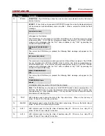
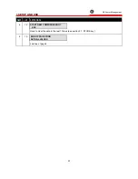
1
G/F CT RATIO :5 ? XXX
(NO indicates 2000:1)
YES (5 amp secondary) or NO (2000:1)
3.11
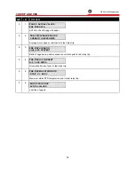
1
G/F CT RATIO
G/F CT = XXX:5
50-250 (increments of 50)
(Not seen if ratio is 2000:1)
3.11
1
GROUND FAULT ALARM LEVEL
G/F ALARM= XXX AMPS
2000:1 CT: 1.0-10.0 amps or OFF (steps of 1.0)
5 A secondary CT: 10-100% of primary amps or
OFF (increments of 10%)
3.11
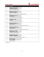
1
G/F ALARM TIME DELAY
TIME DELAY = XXX SEC
1-255 seconds (increments of 1)
3.11
1
GROUND FAULT TRIP LEVEL
G/F TRIP = XXX AMPS
2000:1 CT: 1.0-10.0 A or OFF (steps of 1.0)
5 A secondary CT: 10-100% of primary amps or
OFF (increments of 10% )
3.11
Summary of Contents for 169
Page 12: ......
Page 14: ...2 INSTALLATION g GE Power Management 8 Figure 2 2 CT Dimensions ...
Page 17: ...2 INSTALLATION g GE Power Management 11 Figure 2 4 Relay Wiring Diagram AC control power ...
Page 19: ...2 INSTALLATION g GE Power Management 13 Figure 2 6 Relay Wiring Diagram Two Phase CTs ...
Page 20: ...2 INSTALLATION g GE Power Management 14 Figure 2 7 Relay Wiring Diagram DC Control Power ...
Page 28: ...2 INSTALLATION g GE Power Management 22 Figure 2 10 169 Drawout Relay Physical Dimensions ...
Page 29: ...2 INSTALLATION g GE Power Management 23 Figure 2 11 169 Drawout Relay Mounting ...
Page 31: ...3 SETUP AND USE g GE Power Management 25 Figure 3 1 Front Panel Controls and Indicators ...
Page 73: ...3 SETUP AND USE g GE Power Management 67 Figure 3 2 Standard Overload Curves ...
Page 74: ...3 SETUP AND USE g GE Power Management 68 A B Figure 3 3 Custom Curve Examples ...
Page 88: ...5 THEORY OF OPERATION g GE Power Management 82 Figure 5 1 Hardware Block Diagram ...
Page 90: ...5 THEORY OF OPERATION g GE Power Management 84 Figure 5 2 Firmware Block Diagram ...

