3 SETUP AND USE
g
GE Power Management
53
3$*(
'(6&5,37,21
5
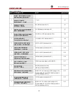
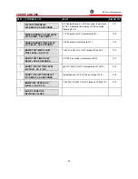
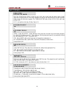
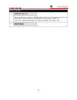
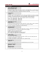
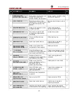
Enable Single-shot
restart ? XXX
(model 169 Plus only) This setpoint is used to enable or defeat the single-shot restart feature described
in section 3.22.
YES - Single-shot restart enabled; NO - Single-shot restart disabled. Factory Value = NO
5
Enable start inhibit?
XXX
(model 169 Plus only) This setpoint is used to enable or defeat the Start Inhibit feature of the relay
described in section 3.20:
YES - Start Inhibit enabled; NO – Start Inhibit disabled
Note: This setpoint should not be changed until the 169 relay has obtained a reasonable value
for the "LEARNED Start Capacity required" (SETPOINTS mode, page 6).
Factory Value = NO
5
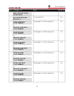
Enable special external
reset function? XXX
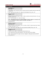
(model 169 Plus only) This setpoint is used to enable or defeat the special external reset feature
described in sections 2.13, 3.22.
YES - special external reset enabled; NO - special external reset disabled. Factory Value = NO
5
Enable phase reversal?
XXX
This code is used to defeat or enable the Phase Reversal Trip function.
YES - Phase Reversal Trip function enabled; NO - Phase Reversal Trip function disabled
Note: If only two phase CTs are used, as shown in Figure 2-6, this setpoint must be set to NO.
Factory Value = NO
Summary of Contents for 169
Page 12: ......
Page 14: ...2 INSTALLATION g GE Power Management 8 Figure 2 2 CT Dimensions ...
Page 17: ...2 INSTALLATION g GE Power Management 11 Figure 2 4 Relay Wiring Diagram AC control power ...
Page 19: ...2 INSTALLATION g GE Power Management 13 Figure 2 6 Relay Wiring Diagram Two Phase CTs ...
Page 20: ...2 INSTALLATION g GE Power Management 14 Figure 2 7 Relay Wiring Diagram DC Control Power ...
Page 28: ...2 INSTALLATION g GE Power Management 22 Figure 2 10 169 Drawout Relay Physical Dimensions ...
Page 29: ...2 INSTALLATION g GE Power Management 23 Figure 2 11 169 Drawout Relay Mounting ...
Page 31: ...3 SETUP AND USE g GE Power Management 25 Figure 3 1 Front Panel Controls and Indicators ...
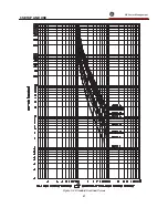
Page 73: ...3 SETUP AND USE g GE Power Management 67 Figure 3 2 Standard Overload Curves ...
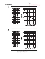
Page 74: ...3 SETUP AND USE g GE Power Management 68 A B Figure 3 3 Custom Curve Examples ...
Page 88: ...5 THEORY OF OPERATION g GE Power Management 82 Figure 5 1 Hardware Block Diagram ...
Page 90: ...5 THEORY OF OPERATION g GE Power Management 84 Figure 5 2 Firmware Block Diagram ...

