1 INTRODUCTION
g
GE Power Management
1
1.1 Motor Protection Requirements
Three phase AC motors have become standard in modern industry. These motors are generally rugged and very
reliable when used within their rated limits. Newer motors, however, tend to be designed to run much closer to these
operational limits and thus, there is less margin available for any type of abnormal supply, load, or operating
conditions.
To fully protect these motors, a modern protective device is required. Accurate stator and rotor thermal modeling is
necessary to allow the motor to operate within its thermal limits and still give the maximum desired output. As well,
other features can be incorporated into a modern relay to fully protect the motor, the associated mechanical system,
and the motor operator from all types of faults or overloads.
Motor thermal limits can be exceeded due to increased current from mechanical overloads or supply unbalance.
Unbalance can greatly increase heating in the rotor because of the large negative sequence current components
present during even small voltage unbalances. A locked or stalled rotor can cause severe heating because of the
associated large currents drawn from the supply. Many motor starts over a short period of time can cause
overheating as well. Phase-to-phase and phase-to-ground faults can also cause damage to motors and hazards to
personnel. Bearing overheating, loss of load, and phase reversal can cause damage to the mechanical load being
driven by the motor.
The ideal motor protection relay should monitor the rotor and stator winding temperatures exactly and shut off the
motor when thermal limits are reached. This relay should have an exact knowledge of the temperature and proper
operating characteristics of the motor and should shut down the motor on the occurrence of any potentially
damaging or hazardous condition.
The Multilin Model 169 Motor Management Relay uses motor phase current readings combined with stator RTD
temperature readings to thermally model the motor being protected. In addition, the 169 takes into account the
heating effects of negative sequence currents in the rotor, and calculates the cooling times of the motor. The relay
also monitors the motor and mechanical load for faults and problems.
1.2 169 Relay Features
The Multilin Model 169 Motor Management Relay is a modern microcomputer-based product designed to provide
complete, accurate protection for industrial motors and their associated mechanical systems. The 169 offers a wide
range of protection, monitoring, and diagnostic features in a single, integrated package. All of the relay setpoints
may be programmed in the field using a simple 12 position keypad and 48 character alphanumeric display. A built-in
"HELP" function can instruct the user on the proper function of each of the programming keys and on the meaning of
each displayed message.
One 169 relay is required per motor. Phase and ground fault currents are monitored through current transformers so
that motors of any line voltage can be protected. The relay is used as a pilot device to cause a contactor or breaker
to open under fault conditions; that is, it does not carry the primary motor current.
The relay comes in two different models, thus allowing for choice of the most cost effective relay for each application.
The 169 Plus has the following features which the model 169 does not: custom curve selectability, motor statistical
records, speed switch input, differential relay input, two auxiliary output relays, two additional RTD inputs, single shot
emergency restart feature, an RS 422 communications port, unbalance input to thermal memory, start inhibit feature,
and spare input terminals.
The custom curve feature of the model 169 Plus gives the user additional flexibility. If one of the eight standard
overload curves is not suitable for the application under consideration, the user can enter his own breakpoints to
form a custom curve. This means that the 169 Plus can offer optimum motor protection in situations where other
relays cannot. Such applications include induced fan drives where the motor stator and rotor thermal capacities can
differ significantly.
An important feature of the Multilin 169 Plus relay, is its ability to "learn" individual motor parameters. The relay
actually adapts itself to each application by "learning" values of motor inrush current, negative sequence current K
factor, cooldown rates, and acceleration time. These values may be used to improve the 169's protective
capabilities (when enabled) and are continually updated. The model 169 learns inrush current only.
The 169 Plus calculates both positive and negative sequence currents. The equivalent motor heating current is
calculated based on the "learned" K factor. This, combined with RTD temperature readings by a motor thermal
modeling algorithm, gives the 169 Plus a complete thermal model of the motor being protected. Thus, the 169 Plus
will allow maximum motor power output while providing complete thermal protection.
Summary of Contents for 169
Page 12: ......
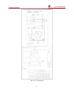
Page 14: ...2 INSTALLATION g GE Power Management 8 Figure 2 2 CT Dimensions ...
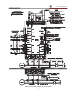
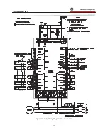
Page 17: ...2 INSTALLATION g GE Power Management 11 Figure 2 4 Relay Wiring Diagram AC control power ...
Page 19: ...2 INSTALLATION g GE Power Management 13 Figure 2 6 Relay Wiring Diagram Two Phase CTs ...
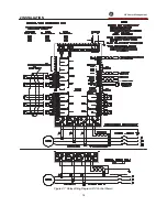
Page 20: ...2 INSTALLATION g GE Power Management 14 Figure 2 7 Relay Wiring Diagram DC Control Power ...
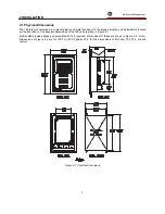
Page 28: ...2 INSTALLATION g GE Power Management 22 Figure 2 10 169 Drawout Relay Physical Dimensions ...
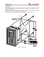
Page 29: ...2 INSTALLATION g GE Power Management 23 Figure 2 11 169 Drawout Relay Mounting ...
Page 31: ...3 SETUP AND USE g GE Power Management 25 Figure 3 1 Front Panel Controls and Indicators ...
Page 73: ...3 SETUP AND USE g GE Power Management 67 Figure 3 2 Standard Overload Curves ...
Page 74: ...3 SETUP AND USE g GE Power Management 68 A B Figure 3 3 Custom Curve Examples ...
Page 88: ...5 THEORY OF OPERATION g GE Power Management 82 Figure 5 1 Hardware Block Diagram ...
Page 90: ...5 THEORY OF OPERATION g GE Power Management 84 Figure 5 2 Firmware Block Diagram ...


