3 SETUP AND USE
g
GE Power Management
73
3.25 Factory Setpoints
When the 169 relay is shipped it will have all setpoints stored in its non-volatile memory. The factory setpoints
represent values for an average large three phase motor. The preset Relay and System Configurations represent
the most common output relay configurations and attributes. These values are meant to be used as a starting point
for programming the relay and should be changed as each application requires.
In the event of a non-volatile memory failure, which will be detected by the self-test feature (see section 3.23), the
169 relay will reload the factory setpoints but will not provide motor protection.
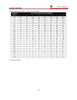
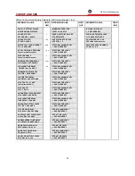
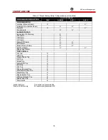
A list of the motor current, RTD, and overload curve setpoints is given in Table 3-6. For other factory setpoints see
Tables 3-7 and 3-3.
Summary of Contents for 169
Page 12: ......
Page 14: ...2 INSTALLATION g GE Power Management 8 Figure 2 2 CT Dimensions ...
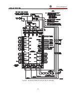
Page 17: ...2 INSTALLATION g GE Power Management 11 Figure 2 4 Relay Wiring Diagram AC control power ...
Page 19: ...2 INSTALLATION g GE Power Management 13 Figure 2 6 Relay Wiring Diagram Two Phase CTs ...
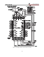
Page 20: ...2 INSTALLATION g GE Power Management 14 Figure 2 7 Relay Wiring Diagram DC Control Power ...
Page 28: ...2 INSTALLATION g GE Power Management 22 Figure 2 10 169 Drawout Relay Physical Dimensions ...
Page 29: ...2 INSTALLATION g GE Power Management 23 Figure 2 11 169 Drawout Relay Mounting ...
Page 31: ...3 SETUP AND USE g GE Power Management 25 Figure 3 1 Front Panel Controls and Indicators ...
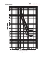
Page 73: ...3 SETUP AND USE g GE Power Management 67 Figure 3 2 Standard Overload Curves ...
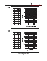
Page 74: ...3 SETUP AND USE g GE Power Management 68 A B Figure 3 3 Custom Curve Examples ...
Page 88: ...5 THEORY OF OPERATION g GE Power Management 82 Figure 5 1 Hardware Block Diagram ...
Page 90: ...5 THEORY OF OPERATION g GE Power Management 84 Figure 5 2 Firmware Block Diagram ...

