6 APPLICATION EXAMPLES
g
GE Power Management
85
6.1 169 Relay Powered from One of Motor Phase Inputs
If a 169 relay is powered from one of the three motor phase inputs, a single-phase condition could cause control
power to be removed from the relay. In order to ensure that the motor is taken off-line if this condition arises, the 169
output relay (e.g. TRIP, AUX. 1) used to trip the motor must change state when control power is removed from the
169. This is accomplished by making this output relay fail-safe. Factory defaults are:
•
TRIP: Fail-Safe
•
ALARM: Non-fail-safe
•
AUX. 1: Non-fail-safe
•
AUX. 2: Non-fail-safe
These can be changed using the RELAY FAILSAFE CODE in page 5 of SETPOINTS mode.
6.2 Loss of Control Power Due to Short Circuit or Ground Fault
If the input voltage (terminals 41-43) to a 169 relay drops below the low-end specification (90 VAC on 120 VAC
units), the 169 output relays will return to their power down states. If the input voltage drops due to a short circuit or
ground fault on a motor, the 169 relay protecting the motor may or may not be able to trip out the motor. For
example, if a 120 VAC 169 relay is set to trip after 0.5 seconds of an 8.0 XFLC short circuit current, the input voltage
must remain above 90 VAC for at least 0.5 seconds after the short circuit has occurred or else the 169 relay will not
be able to trip. As explained in section 6.1 above, in order to trip the motor when control power for the 169 is lost,
the 169 output relay used to trip the motor must be configured as fail-safe.
Summary of Contents for 169
Page 12: ......
Page 14: ...2 INSTALLATION g GE Power Management 8 Figure 2 2 CT Dimensions ...
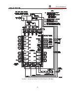
Page 17: ...2 INSTALLATION g GE Power Management 11 Figure 2 4 Relay Wiring Diagram AC control power ...
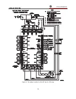
Page 19: ...2 INSTALLATION g GE Power Management 13 Figure 2 6 Relay Wiring Diagram Two Phase CTs ...
Page 20: ...2 INSTALLATION g GE Power Management 14 Figure 2 7 Relay Wiring Diagram DC Control Power ...
Page 28: ...2 INSTALLATION g GE Power Management 22 Figure 2 10 169 Drawout Relay Physical Dimensions ...
Page 29: ...2 INSTALLATION g GE Power Management 23 Figure 2 11 169 Drawout Relay Mounting ...
Page 31: ...3 SETUP AND USE g GE Power Management 25 Figure 3 1 Front Panel Controls and Indicators ...
Page 73: ...3 SETUP AND USE g GE Power Management 67 Figure 3 2 Standard Overload Curves ...
Page 74: ...3 SETUP AND USE g GE Power Management 68 A B Figure 3 3 Custom Curve Examples ...
Page 88: ...5 THEORY OF OPERATION g GE Power Management 82 Figure 5 1 Hardware Block Diagram ...
Page 90: ...5 THEORY OF OPERATION g GE Power Management 84 Figure 5 2 Firmware Block Diagram ...

