5HY&
0DUFK
6XSHU%XV;/&'$OSKDQXPHULF7RXFKSDG
,QVWDOODWLRQ,QVWUXFWLRQV
3URGXFW6XPPDU\
The SuperBus
®
2000 2x16 LCD (liquid crystal display) Alpha-
numeric Touchpad lets you control all programming and opera-
tion of a compatible security system (see the section
“Specifications”). The 2-line, 16-character display provides
messages to indicate the current system status.
The touchpad includes police, fire, and auxiliary panic buttons
that can be activated anytime.
A built in speaker provides alarm sounds, status sounds, and
button-press beeps.
,QVWDOODWLRQ
,QVWDOODWLRQ*XLGHOLQHV
• Mount the touchpad in an environmentally controlled area
32°F to 120°F (0°C to 49°C).
• When mounting the touchpad, allow at least 4¼ inches on
the left side for the Quick Guide slide-out card.
• For Concord
™
Express systems, up to 4 bus devices can be
connected to the panel. For Concord systems (all software
versions and Concord Express version 4) up to 16 bus
devices can be connected to the panel.
• For Concord systems with software versions 1.0–1.6, each
bus device must have a different unit number setting to
operate correctly. The touchpad unit number is factory set to
001. For Concord panels with software version 2.0 or later
and Concord Express panels, bus unit numbers are assigned
automatically.
• Table 1 describes the power used by the touchpad.
• Do not exceed the maximum available power when using
panel power for bus devices and hardwire detectors (see the
specific panel
Installation Instructions
for maximum avail-
able power).
• Table 2 describes the maximum wire lengths allowed
between the touchpad and panel.
7RROVDQG(TXLSPHQW1HHGHG
• 4-conductor, 22- or 18-gauge wire
• Screwdriver
• Drill/bits
• #6 screws and anchors (included)
• Panhead screws for a gang box installation
• Saw or utility knife for cutting wallboard
,QVWDOOLQJWKH0RXQWLQJ3ODWH
The touchpad can be installed on a wall or electrical gang box,
either single- or dual-gang.
1.
Separate the mounting plate from the touchpad by pressing
the tab at the bottom and sliding the mounting plate down
(see Figure 1).
)LJXUH
6HSDUDWLQJ7RXFKSDG)URP0RXQWLQJ3ODWH
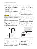
2.
Place the mounting plate on the wall and mark the four
mounting holes (see Figure 2). Be sure to leave a 4¼-inch
clearance on the left side to allow for the Quick Guide slide-
out card.
)LJXUH
0ROHV
3.
Insert anchors at the marked locations where studs are not
present.
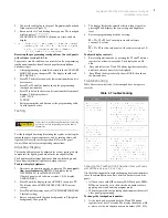
4.
Looking at the back side of the mounting plate, turn it so the
tab is on the left (see
A
in Figure 3) and position the Quick
Guide slide-out card into the slots on back of the mounting
plate as shown in Figure 3 (
A
). Make sure the card is
unfolded and the “Zones” section is facing you.
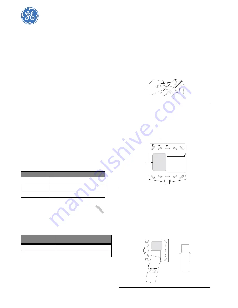
5.
Slide the card in the direction of the arrow in Figure 3 (
A
)
until it snaps into the position shown in Figure 3 (
B
)
)LJXUH
,QVHUWLQJWKH4XLFN*XLGH6OLGH2XW&DUG
7DEOH
7RXFKSDG3RZHU8VDJH
&XUUHQWP$
&RQGLWLRQ
0D[LPXPDODUPFXUUHQW
7\SLFDORSHUDWLRQ
6WDQGE\FXUUHQWQR$&SRZHU
7DEOH
0D[LPXP7RXFKSDG:LUH/HQJWKV
:LUH*DXJH8QVKLHOGHG
RU6KLHOGHG
0D[LPXP:LUH/HQJWK%HWZHHQ7RXFKSDG
DQG3DQHO
IHHW
IHHW
Lift and Pull
Mounting Plate
Tab
Tab
Wall Mounting Holes (4)
Dual-Gang Mounting Holes (4)
Single-Gang Mounting Holes (4)
Wire Access Area
Swing card over in
Direction of Arrow
Until Card Snaps into Place
A
B


