6XSHU%XV
;/&'$OSKDQXPHULF7RXFKSDG
,QVWDOODWLRQ,QVWUXFWLRQV
6.
Position the mounting plate in its normal mounting position
(tab at the bottom) and fold the card toward you at all three
scored lines. The “Zones” section should be facing you and
the folds should create a tab to slide the card in and out.
7.
Align the mounting plate wall-mount holes with the wall
anchors and secure the back-plate to the wall using the
screws provided.
OR
If installing the back-plate on an electrical gang box, line up
the appropriate gang box holes on the mounting plate with
the gang box holes and secure the back-plate to the gang
box using the screws provided.
8.
For wall-mounted installations, cut a hole in the wall in the
wire access area of the mounting plate to pull your cable
through for wiring.
:LULQJ
Wiring consists of connecting the touchpad to the panel termi-
nals.
1.
Disconnect the panel transformer and backup battery.
2.
Run a 4-conductor, 18- to 22-gauge wire from the panel to
the touchpad location.
3.
Splice the 4-conductor cable wires to the red, black, green,
and white wires located on the back of the touchpad.
4.
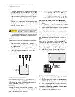
Connect the touchpad wiring to the panel terminals as
shown in Figure 4.
)LJXUH
:LULQJ7RXFKSDGWR3DQHO7HUPLQDOV
$WWDFKLQJWKH7RXFKSDGWRWKH0RXQWLQJ3ODWH
Align the four slots on the touchpad with the four tabs on the
mounting plate and slide the keypad down until you hear the
latch on the mounting plate click into place.
3RZHU8S
After making all wiring connections from the touchpad to the
panel, you are ready to power up the panel. Upon power up, the
panel scans the bus for connected devices and automatically
learns the unit number of each bus device.
1RWH
,I\RXSODQRQLQVWDOOLQJV\VWHPVZLWKQRDOSKDQXPHULF
WRXFKSDGVLWLVUHFRPPHQGHGWKDW\RXNHHSDQ
DOSKDQXPHULFWRXFKSDGZLWK\RXVSHFLILFDOO\IRU
SURJUDPPLQJ7KLVWRXFKSDGFDQEHTXLFNO\FRQQHFWHG
DQGGLVFRQQHFWHGIURPWKHKHDGHUSLQVRQWKHORZHU
SRUWLRQRIWKHSDQHOFLUFXLWERDUGDVGHVFULEHGODWHULQ
WKLVGRFXPHQW
To power up the panel and verify bus communication:
1.
Verify that all wiring between the panel and touchpad is
correct.
1RWH
,IWKHWRXFKSDGGRHVQRWGLVSOD\WKHGDWHDQGWLPHVHH
´7URXEOHVKRRWLQJµ
2.
Connect the panel battery and plug in the panel transformer.
Alphanumeric touchpads should show a date and time
display.
&RQQHFWLQJWKH7RXFKSDGIRU6\VWHP3URJUDPPLQJ
2QO\
For installations that don’t include an alphanumeric touchpad as
a permanent part of the system, you can connect one for system
programming to the Programming Touchpad Header on the
panel.
To do this you must first connect a Programming Touchpad
Cable (60-791) to the touchpad wires (see
Programming
Touchpad Cable Installation Instructions—466-1604
, included
with the cable). Then, use the appropriate procedure for
connecting the touchpad.
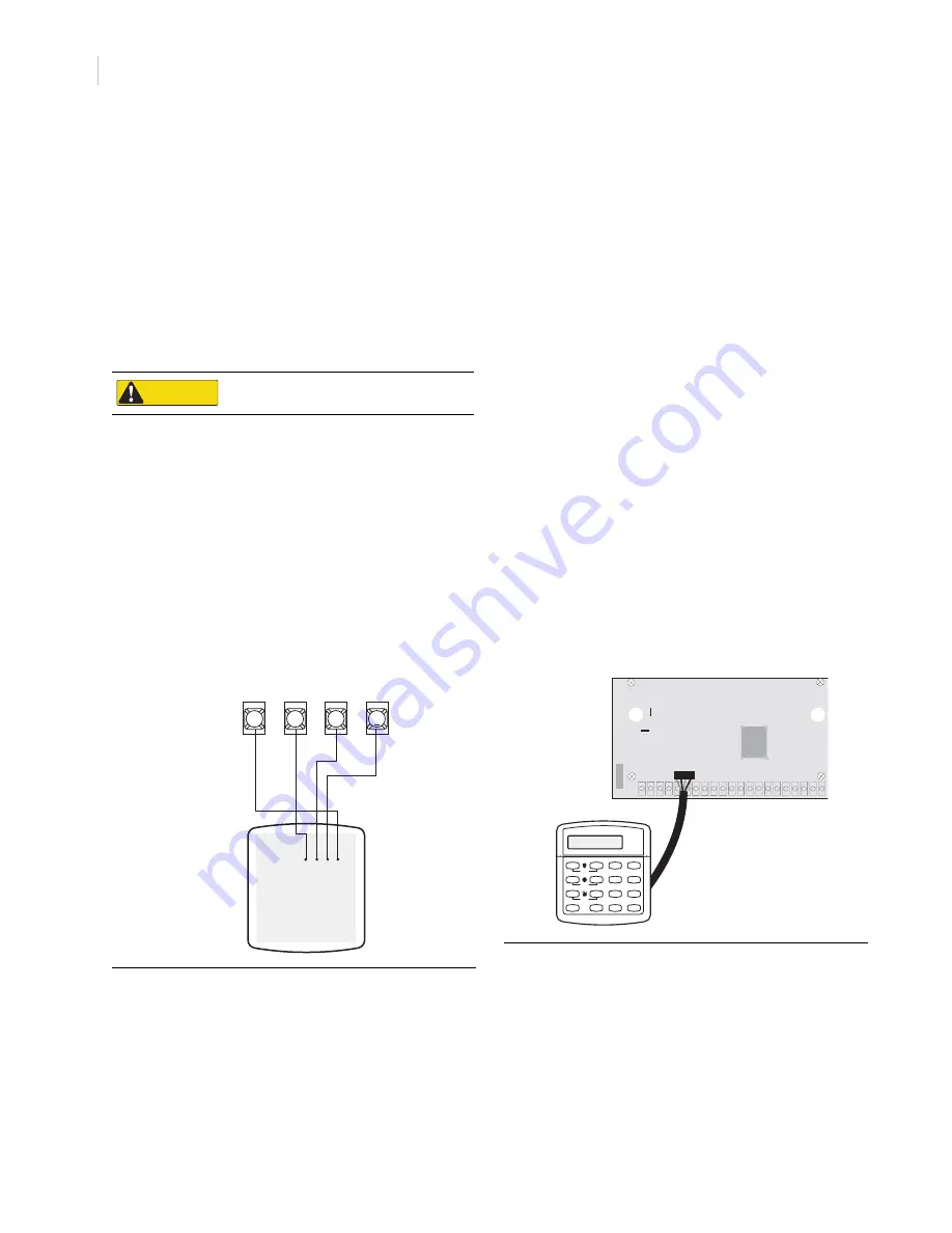
To connect a programming touchpad to a Concord Express
or Concord panel with software version 2.0 or later:
1.
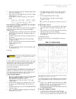
With the panel powered up, connect the cable to the
Programming Touchpad Header (see Figure 5).
)LJXUH
&RQQHFWLQJD3URJUDPPLQJ7RXFKSDG
2.
Activate the service touchpad by pressing
8
+
CODE
+
0
+
2
.
3.
Enter program mode by pressing
8
+ installer/dealer
CODE
+
0
+
0
and program the panel using the panel
Installation Instructions.
4.
When programming is completed, simply disconnect the
programming touchpad.
To connect a programming touchpad to a Concord panel
with software versions 1.0–1.6:
1.
Disconnect AC and backup battery power.
CAUTION
Do not overtighten screws or the back plate may bend
and prevent the touchpad from mounting properly.
3
4
5
6
BACK OF
TOUCHPAD
G
N
D
/BLAC
K
+12V/
R
ED
BU
S
A/
G
R
EE
N
BU
S
B/
W
H
ITE
+12V
A
B
GND
BUS
S t a t u s
F e a t u r e s
p r e s s b o t h
L i g h t s
S y s t e m
A w a y
Q u i c k E x i t
O f f
N o D e l a y
p r e s s b o t h
p r e s s b o t h
T e s t S y s t e m W e e k l y
S i l e n t
S t a y
D
*
7
0
#
8
B
A
4
1
5
6
2
3
B y p a s s
M e n u
C
9
P R O G R A M M I N G
T O U C H P A D
C A B L E ( 6 0 - 7 9 1 )
Programming
Touchpad
Cable (60-791)


