26
Generator ac connection system
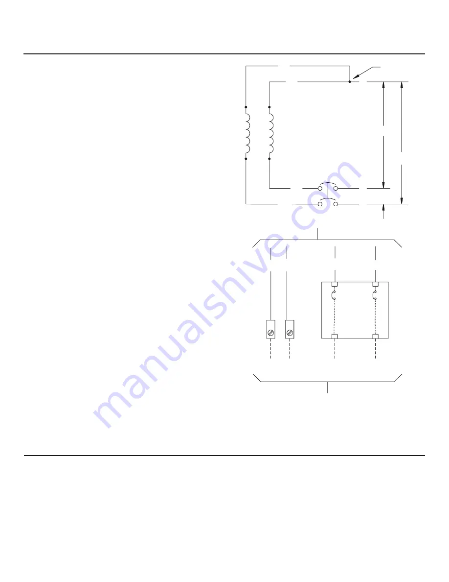
A single-phase, three-wire AC connection system is used in
the home generator. The stator assembly consists of a pair
of stationary windings with two leads brought out of each
winding. The junction of leads 22 and 33 forms the neutral
lead, as shown schematically and as a wiring diagram. A
complete schematic and wiring diagram can be found later
in this manual.
NOTICE
Neutral is not bonded to ground at generator.
NOTICE
Generator must be used with only an UL approved
transfer switch that is compatible with the generator.
33
240V
11
22
44
120V
120V
11
22
44
0
Neutral
Pow
er W
inding
Circuit
Breaker
Line 1
Neutral
To Transfer Switch
Line 2
Ground
Circuit
Breaker
Grounding the Generator
From Alternator Power Windings
The home generator must be installed as part of a system
that includes a listed transfer switch, with neutral to
ground bonding at the transfer switch in accordance
with installation instructions. Unless mandated by local
code, additional grounding to earth at the generator is
not required. Any grounding at generator must use metal
piercing lock washers (or equal), UL listed terminals installed
per terminal supplier’s instructions, and comply with national
electrical codes and local requirements.
NOT
for
REPRODUCTION
Summary of Contents for 20 kW Home
Page 10: ...10 Intentionally Left Blank N O T f o r R E P R O D U C T I O N ...
Page 41: ...41 NOTES N O T f o r R E P R O D U C T I O N ...
Page 42: ...42 NOTES N O T f o r R E P R O D U C T I O N ...
Page 43: ...43 Schematic Diagram Schematic Wiring Diagrams N O T f o r R E P R O D U C T I O N ...


