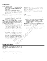
34
initial start-up (no Load)
The unit has been set-up for NG operation at the factory.
Fuel conversion, if needed, must be completed prior to
performing these steps. See Fuel Conversion.
Before operating the home generator or placing it into
service, inspect the entire installation carefully. Then begin
testing the system without any electrical loads connected,
as follows:
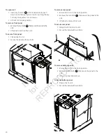
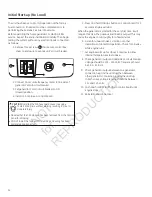
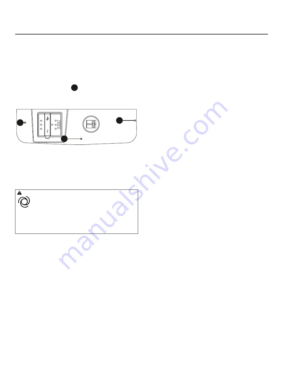
1. Remove three screws
a
that secure control box
cover to enclosure to expose unit’s circuit breaker.
A
A
2. Connect an accurate frequency meter to line side of
generator’s main circuit breaker.
3. Set generator’s main circuit breaker to ON
(closed) position.
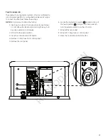
4. Install 15 Amp fuse in control board.
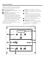
5. Press and hold MANUAL button on control board for 3
seconds. Engine will start.
When the generator is started for the very first time, it will
require that air in the gaseous fuel lines be purged. This may
cause the engine to run roughly for a few minutes.
6. Listen for unusual noises, vibration or other
indications of abnormal operation. Check for oil leaks
while engine runs.
7. Let engine warm up for about 5 minutes to allow
internal temperatures to stabilize.
8. Check generator output at load side of circuit breaker.
Voltage should be 225 - 250 Volts, frequency should
be 59.0 - 61.0 Hz.
9. Check generator output between one generator
connection lug and neutral lug, then between
other generator connection lug and neutral lug.
In both cases, voltage reading should be between
112 and 125 Volts.
10. Push and hold OFF BUTTON on control board until
engine stops.
11. Reinstall control box cover.
caution
Installing the 15A fuse could cause the engine
to start at any time without warning resulting in minor or
moderate injury.
• Observe that the 15 Amp fuse has been removed from the control
panel for shipping.
• DO NOT install this fuse until all plumbing and wiring has been
completed and inspected.
A
NOT
for
REPRODUCTION
Summary of Contents for 20 kW Home
Page 10: ...10 Intentionally Left Blank N O T f o r R E P R O D U C T I O N ...
Page 41: ...41 NOTES N O T f o r R E P R O D U C T I O N ...
Page 42: ...42 NOTES N O T f o r R E P R O D U C T I O N ...
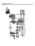
Page 43: ...43 Schematic Diagram Schematic Wiring Diagrams N O T f o r R E P R O D U C T I O N ...

