3
7/28/2011
IMPORTANT SAFETY NOTICE
The information in this presentation is intended for use by individuals
possessing adequate backgrounds of electrical, electronic, & mechanical
experience. Any attempt to repair a major appliance may result in
personal injury & property damage. The manufacturer or seller cannot be
responsible for the interpretation of this information, nor can it assume
any liability in connection with its use.
WARNING
To avoid personal injury, disconnect power before servicing this product.
If electrical power is required for diagnosis or test purposes, disconnect
the power immediately after performing the necessary checks.
RECONNECT ALL GROUNDING DEVICES
If grounding wires, screws, straps, clips, nuts, or washers used to
complete
a path to ground are removed for service, they must be returned to their
original position & properly fastened.
Summary of Contents for 2011 E - Star
Page 1: ...Dishwasher Training 2011 New Door Configuration 2011 E Star ...
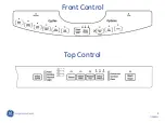
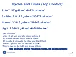
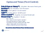
Page 5: ...5 7 28 2011 Front Control Top Control ...
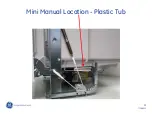
Page 11: ...11 7 28 2011 Mini Manual Location Plastic Tub ...
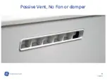
Page 12: ...12 7 28 2011 Passive Vent No Fan or damper ...
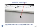
Page 13: ...13 7 28 2011 Indicator Lamp Lens Solid Amber when running Solid Green when Clean ...
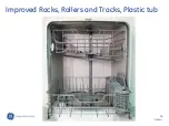
Page 14: ...14 7 28 2011 Improved Racks Rollers and Tracks Plastic tub ...
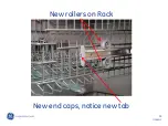
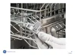
Page 15: ...15 7 28 2011 New rollers on Rack New end caps notice new tab ...
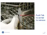
Page 16: ...16 7 28 2011 Push Tab to center to remove ...
Page 17: ...17 7 28 2011 ...
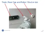
Page 18: ...18 7 28 2011 Track Rear Cap and Roller Stud on tub ...
Page 19: ...19 7 28 2011 Door Strike Catch is non adjustable ...
Page 20: ...20 7 28 2011 Tub TCO location 1 shot with Manual reset Trip at 189 with manual reset ...
Page 21: ...21 7 28 2011 Tub TCO is resettable if tripped Reset TCO replace the control ...
Page 22: ...22 7 28 2011 Fill hose should be inserted 1 1 2 inches ...
Page 23: ...23 7 28 2011 Fill Funnel inside tub ...
Page 24: ...24 7 28 2011 Rotate Clockwise to remove ...
Page 25: ...25 7 28 2011 Fill funnel seal seal ...
Page 26: ...26 7 28 2011 Turn Counterclockwise and lift to remove wash arm ...
Page 27: ...27 7 28 2011 Coarse Filter Fine Filter Hub Nut ...
Page 28: ...28 7 28 2011 Remove nut to remove Fine Filter ...
Page 29: ...29 7 28 2011 Lift Fine Filter to remove ...
Page 30: ...30 7 28 2011 To remove Top Wash Arm and Conduit remove Hex screw Conduit ...
Page 31: ...31 7 28 2011 Lift Tab continue to remove Conduit ...
Page 32: ...32 7 28 2011 Push Conduit back and to side to finish removal being careful to not break tab ...
Page 33: ...33 7 28 2011 To remove Sump Cover push in 4 tabs and lift cover ...
Page 34: ...34 7 28 2011 To Remove sump filter the tabs can be released with a screwdriver or putty knife ...
Page 35: ...35 7 28 2011 Push Sump Filter to right and lift to remove ...
Page 36: ...36 7 28 2011 Tab location for cover and filter removal Cover tabs Sump Tabs ...
Page 38: ...38 7 28 2011 With hub removed Coarse Filter can now be removed ...
Page 39: ...39 7 28 2011 Coarse Filter removal ...
Page 40: ...40 7 28 2011 Proper location of the Wash Arm Bearing or Thrust Washer ...
Page 41: ...41 7 28 2011 Make sure the Bearing or Thrust Washer is in place when re assembled ...
Page 43: ...43 7 28 2011 Float Dome to remove simply lift ...
Page 44: ...44 7 28 2011 Float Stem activates Flood Switch below ...
Page 49: ...49 7 28 2011 Shield folded back to show control TCO located on cover 1 shot Trip at 280 ...
Page 51: ...51 7 28 2011 Cover removal 1 lift top and pull out 2 push bottom down 1 2 ...
Page 53: ...53 7 28 2011 Model Select MUST be Transferred or new control will not operate just flash ...
Page 54: ...54 7 28 2011 Insulator between control board and console Must be installed ...
Page 56: ...56 7 28 2011 Handle can now be removed from the front ...
Page 57: ...57 7 28 2011 Tactile switch has 2 screws securing switch to console ...
Page 59: ...59 7 28 2011 Buttons and Silicone Pad come as an assembly ...
Page 60: ...60 7 28 2011 Notice buttons are keyed they fit one way ...
Page 62: ...62 7 28 2011 To Remove Door Switch assembly unscrew 2 screws Insulator MUST be used ...
Page 64: ...64 7 28 2011 Door Switch comes as an assembly 2 switches and bracket actuator ...
Page 66: ...66 7 28 2011 Pry the old vent louver off of the outer door ...
Page 67: ...67 7 28 2011 Remove any excess adhesive from the outer door Dispose old vent ...
Page 68: ...68 7 28 2011 Install new vent on clean panel ...
Page 69: ...69 7 28 2011 Console can be removed when Control Pocket Handle and Vent have been removed ...
Page 70: ...70 7 28 2011 Console removed ...
Page 71: ...71 7 28 2011 Lens Adhered with double back tape Console must be removed to access lens ...
Page 73: ...73 7 28 2011 Correct water level Main wash is suggested time to check for proper level ...
Page 74: ...74 7 28 2011 ...
Page 75: ...75 7 28 2011 ...
Page 76: ...76 7 28 2011 Schematic ...
Page 79: ...79 7 28 2011 Mini Manual Location Stainless Tub ...
Page 83: ...83 7 28 2011 Door catch is non adjustable ...
Page 84: ...84 7 28 2011 Door separated there are no hangers to balance the door as on previous models ...
Page 87: ...87 7 28 2011 Single door switch breaks line side ...
Page 89: ...89 7 28 2011 The vent is keyed but in the middle The vent can be installed incorrectly ...
Page 90: ...90 7 28 2011 SS Vent correctly installed Correct positioning ...
Page 94: ...94 7 28 2011 Service Mode SS ...
Page 95: ...95 7 28 2011 SS Schematic ...
Page 96: ......


