ii
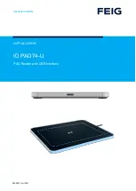
GE Contactless Smart Card Reader Model 24x
Figures
Figure 1:
GE Contactless Smart Card Reader Model 240 ............ 1
Figure 2:
GE Contactless Smart Card Reader Model 245 ............ 2
Figure 3:
GE Model 24x Reader Backplate
(includes tamper switch magnet) ................................... 3
Figure 4:
Isolation Spacer ............................................................. 4
Figure 5:
GE Model 24x Backplate and Snap-on cover ................ 7
Figure 6:
Back-to-Back/Center-to-Center Installation.................... 8
Figure 7:
GE Model 24x Reader Wiring Diagram to
Micro/5 8RP ................................................................. 12
Figure 8:
Model 24x Smart Card Reader Wiring Diagram
to J-Box ........................................................................ 13
Figure 9:
GE Model 24x Reader to 2RP...................................... 14
Figure 10: GE Model 24x Reader to 8RP...................................... 16
Figure 11: GE Model 240x Reader to Micro.................................. 18
Figure 12: Stripping of Shield Grounds ......................................... 23
Summary of Contents for 240
Page 1: ......
Page 6: ......
Page 7: ......
Page 9: ...4 GE Contactless Smart Card Reader Model 24x FIGURE 4 Isolation Spacer ...
Page 19: ......
Page 21: ......
Page 30: ...GE Contactless Smart Card Reader Model 24x 25 ...
Page 31: ...26 GE Contactless Smart Card Reader Model 24x ...
Page 32: ...GE Contactless Smart Card Reader Model 24x 27 ...
Page 33: ...28 GE Contactless Smart Card Reader Model 24x ...


