
49-Tomberlin Emerge (262E1_262TB1_403TB1) Install Sheet-370 Rev 02 11/29/18
Sheet 3 of 4
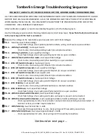
Tomberlin Emerge Troubleshooting Sequence
FOR SAFETY, ALWAYS LIFT THE DRIVE WHEELS OFF THE GROUND WHEN TROUBLESHOOTING!
ALL TESTS ARE CONDUCTED WITH RUN-TOW/MAINTENANCE SWITCH IN THE RUN POSITION AND WITH A GOOD
BATTERY PACK VOLTAGE MEASUREMENT. ALSO, THE CONNECTOR MUST BE ATTACHED TO THE CONTROLLER
WHEN MAKING THESE CHECKS. YOU WILL NEED TO ‘BACK PROBE’ THE PINS FROM THE WIRE SIDE OF THE
CONNECTOR. USE A PAPERCLIP IF NECESSARY.
Attach voltmeter negative (-) lead to main Battery Negative (-) for the following tests.
Use the following sequence when checking individual pins (don’t skip steps). If you find a fault, do not move on
to the next step until the fault is corrected:
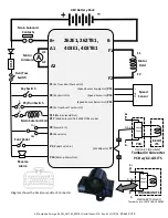
Measure the voltage at the main battery positive post (let’s call it Pack Voltage)
Pin 1 Must be equal to Pack Voltage
-
If not Pack Voltage, check polarity protection diode, wiring, and Fuse for open condition
Pin 6 With Key Switch Off, must equal 0 volts
-
If not 0 volts, check wiring and Key Switch for a shorted condition
Pin 6 With Key Switch On, must equal Pack Voltage
-
If not Pack Voltage, check wiring and Key Switch for an open condition
Pin 2 With PC/Run Switch in Run mode, must equal Pack Voltage
-
If not 0 volts, check wiring and Pc/Run Switch for an open condition
Pin 4 With F/R Switch in Reverse, must equal 0 volts
-
If not 0 volts, check wiring and F/R Switch for a shorted condition
Pin 4 With F/R Switch in Forward, must equal Pack Voltage
-
If not Pack Voltage, check wiring and F/R Switch for an open condition
Pin 5 With F/R Switch in Forward, must equal 0 volts
-
If not 0 volts, check wiring and F/R Switch for a shorted condition
Pin 5 With F/R Switch in Reverse, must equal Pack Voltage
-
If not Pack Voltage, check wiring and F/R Switch for an open condition
Pin 3 With Pedal Up, must equal 0 volts
-
If not 0 volts, check wiring and Pedal Switch for a shorted condition
Pin 3 With Pedal Down, must equal Pack Voltage
-
If not Pack Voltage, check wiring and Pedal Switch for an open condition
Pin 10 With Direction Switch in Neutral, must equal Pack Voltage
-
If not Pack Voltage, check wiring and make sure beeper is present and connected
Pin 10 With Direction Switch in Reverse, must equal approximately 0 volts (and beeper sounds)
-
If not approximately 0 volts, check connector and wire terminal for being burnt/corroded. If
terminal is clean, controller may be defective
Pin 7 With Pedal Up, must be less than .5 volts
-
If not less than approximately .5 volts, check wiring and ITS assembly connections
Pin 7 With Pedal Fully Down, must equal approximately 5.0 volts
-
If not approximately 5.0 volts, check wiring and ITS assembly connections
Continued on next page …


