10
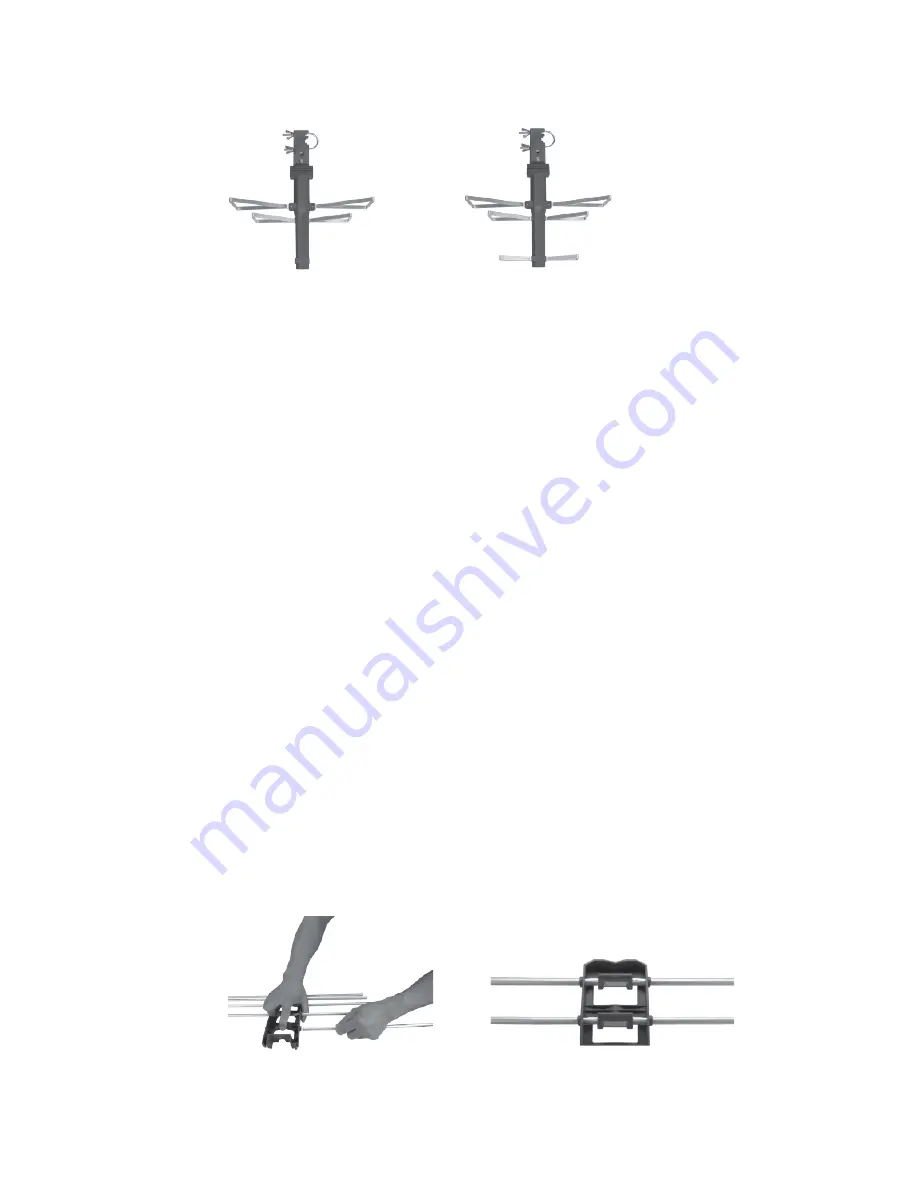
b) Attach in the same manor the
Dipoles “B” and “A” using the
M3 X 8mm Sheet Metal Screws, being careful not to
overtighten the screws (Fig. 2b & Fig. 2c).
Fig. 2b
Fig. 2c
3) Assembling the Reflector
Note: Before assembling the
Reflector, you will notice that the holes on the
Reflector Brackets are not perfectly round and the center of the Reflector
Rods is slightly flat. You will also see to indentations on each rod spaced
about 1.5” apart on all 12 rods; these indentations are there to help in
properly aligning the rods evenly in the
Reflector Brackets.
When assembling the rods into the
Reflector Brackets, do not force the
Reflector Rods into the brackets. Be careful in this part of the assembly so
that you do not bend the
Reflector Rods.
a) Place one half of the
Reflector Bracket on a flat surface with the
clamping tabs facing up and the open end facing away from you.
b) Using your thumb, hold down the
Reflector Bracket and with your
index finger; carefully lift up on the clamping tab.
c) With your other hand, slide one of the
Reflector Rods into the
bracket being sure to slide the
Reflector Rod under the clamping
tab, the rod will stop sliding in when the flat part of the rod reaches
the opening on the
Reflector Bracket. At this point, slightly twist
the reflector rod until the flat portion of the rod aligns with the flat
part of the hole on the
Reflector Bracket. Finish sliding in the
Reflector Rod until the clamping tab is in the middle of the two
indentations (Fig. 3a & Fig. 3b).
Fig. 3a
Fig. 3b
d) Repeat the above process for the other five
Reflector Rods and the
second half of the
Reflector Bracket and rods.


