background image

Summary of Contents for 36" CUSTOM HOOD INSERT ZVC36LSS

Page 1: ...I I S 30 36 and 48 Custom Hood Insert ZVC3OLSS ZVC36LSS ZVC48LSS 49 80415 I 12 06 JR Monogram ...

Page 2: ...eaning unit switch power off at service panel and lockthe service disconnecting means to prevent power from being switched on accidentallU When the service disconnecting means cannot be locked securelUfasten a prominent warning device such as a tag to the service panel AVERTISSEMENT POURRI_DUIRE LERISQUED INCENDIE DECHOC ELECTRIOUE OU DEBLESSURES CORPORELLES IL FAUTOBSERVER LESREGLES SUIVANTES A U...

Page 3: ...e allowed to accumulate on fan or filter D Use proper pan size Alwags use cookware appropriate for the sizeof the surface element AVERTISSEMENT AFIN DE REDUIRE LE RISQUE D UNFEUDEFRITURE SUR LACUISINIERE A Ne laissezjamaissanssurveillanceles6bments decuissonde votrecuisini_re Iorsqu ils sontr6gl6s_ unetemperature6levee Lesd6bordementscauserontde lafum6eet les6claboussures de graissepeuventprendref...

Page 4: ...stall Damper Plate 19 Step 5 Install Blower Motor 20 Step 6 Connect Wiring Harness 20 Step 7 Install Filters 21 Step 8 Finalize Installation 21 PRODUCT CLEARANCES The vent hood and liner assemblg must be installed 50 minimum and 36 maximum above the cooking surface NOTE Installation height should be measured from the cooking surface to the bottom edge of the metal hood liner or cabinet surface NOT...

Page 5: ...26 MI x 13 3116 D 3 4 thick material must surround the opening to allow the sleeve locking clips to engage The insert sleeve inside the cabinet should be positioned 1 2 from the rear wall so that the center of the 8 duct is 5 1 2 from the rear wall 2 The Insert Sleeve 251 1 2 The bottom edge of the insert sleeve has a 7 8 wide flange on the sides and a 1 2 wide flange on the front and back Remote ...

Page 6: ...a template The opening must be 26 MI x 13 3 16 D 3 4 thick material must surround the opening to allow the sleeve locking clips to engage The insert sleeve inside the cabinet should be positioned 1 2 from the rear wall so that the center of the 8 duct is 5 1 2 from the rear wall 1 2 The bottom edge of the insert sleeve has a 7 8 wide flange on the sides and a 1 2 wide flange on the front and back ...

Page 7: ...s a template The opening must be 38 3 4 W x 13 3 16 D 3 4 thick moterial must surroundthe opening to allow the sleevelocking dips toengage The insert sleeveinside the cabinet should be positioned 112 from the rearwallso thatthe centerofthe 8 duct is5 1 2 from the reor wall The Insert Sleeve 29 1 2 38 1 1 2 A 1 2 wide flange surrounds the outside edge of the insert sleeve Remote Location for the Co...

Page 8: ...of the control mounting assembly A 30 ft wire cord is provided Careful consideration must be given to the location of the remotely mounted control It is recommended that the a wire cord be routed through conduit between the insert sleeve and the remote mounting location POWER SUPPLY IMPORTANT Please read carefully WARNING FOR PERSONAL SAFETY THIS APPLIANCE MUST BE PROPERLYGROUNDED AVERTISSEMENT PO...

Page 9: ...HRAE Actual length of straight duct plus duct fitting equivalent Equivalent length of duct pieces are based on actual tests conducted by GE Evaluation Engineering and reflect requirements for good venting performance with any ventilation hood Equivalent Quantitg Duct Piece Dimensions Length Used Round i ft straight per foot length 3 1 4 x 12 1 ft 3 1 4 x 24 per foot straight length _ 8 round 90 el...

Page 10: ...T SLEEVE OUT OF THE BOX BY GRASPING THE SIDES ATTENTION SOULEVEZ LE HANCHON INTERIEUR DE LA BOITE EN SAISISSANT SESCOTES 1 Open hood carton 2 Remove the liner foam and cardboard 3 Remove the tape securing the filters to the insert sleeve lift the tabs and remove the filters J 4 Unscrew the S nuts securing the damper vent plate assemblg and remove it from the insert sleeve Set the S nuts and the da...

Page 11: ...ert sleeve chassis plugs 1 optional house wire hole plug 2 rubber grommets 4 insert sleeve washers REMOTE MOUNTING OF THE CONTROL WIRED Blanking plate for remote control opening NOTE To be used on custom hood when controls are remotely mounted 30 ft of 4 wire cord straight pinned with connector NOTE Not for telecommunications telephone network Control wall bracket Control Control mounting mounting...

Page 12: ...mper plate assemblg 4 liner height 30 Min 36 Max installation height 5 1 2 from rear wall to centerline Ceiling ducting If ductwork will vent straight up to the ceiling Use a level to draw a centerline straight up to the ceiling On the ceiling measure 5 1 2 from the back wall to the centerline of an 8 2 hole Wall Ducting If ductwork will vent to the rear Use a level to draw a centerline straight u...

Page 13: ... a plumb bob to check the location The countertop cooktop below the insert sleeve must be centered with the insert sleeve The insert sleeve should extend beuond the front and rear edge of the cooking appliance Align with center of cooktop Ceiling Hood ducting centerline Front t 30 Min 36 Max installation i i height j Cooktop i _ _ Countertop The insert sleeve in the ceiling must be centered left t...

Page 14: ...lled in a backsplash or countertop A cover plate is provided to cover the opening in the hood when the control is removed A 30 ft length of 4 wire cord is supplied to accommodate most installations Because onlg 30 ft of cord is provided careful consideration must be given to the location of the remotelg mounted control NOTE Not for telecommunication telephone network The cord must be routed throug...

Page 15: ...16 x 3 11 16 2 Loosen the 4 thumbscrews ond remove the control from the insert sleeve Replace the control with the blonking plote provided 3 Attach the mounting plote to the bock of the control with the 2 mounting plote screws 4 Pull the a wire cord through the opening in the wall the woll brocket ond the back of the mounting brocket NOTE Use provided cable or cable designated bg the National Elec...

Page 16: ...me the cutout opening to fit the linen NOTE The opening support must be 3 4 thick wood to accept the liner installation screws 3 Secure the liner to the cabinet with 6 screws provided 2 Slide the liner up Qnd into the opening until flush with bottom edges 16 ...

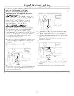
Page 17: ...n est en aluminium assurez vous d utiliser un compos anti oxgdant approuv6 et des raccords aluminium _ cuivre I Place insert sleeve on padded get stable surface below cutout can use flattened carton to pad surface 2 Remove the junction box cover 00000 00000 4 Connect white leads to branch circuit white lead 5 Connect blackleadsto branch circuit blacklead 6 Connect green yellow leads to branch circ...

Page 18: ...ews have been inserted ape 4 Align 8 duct to exhaust opening of insert sleeve and seal with aluminum tape NOTE House duct should drop to 11 1 2 above bottom edge of insert sleeve or the bottom of the 3 4 cabinet base 5 Tape the 4 washers in place over the outside of the 4 front and back holes of the insert sleeve The washers are designed to be located between the insert sleeve and the 3 4 cabinet ...

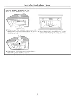
Page 19: ...semblg and rotate so that vent side is up and bracket is located on left as gou 3 Secure damper plate assemblg bg placing nuts stand facing hood on bolts and tightening with socket or wrench 2 Insert damper plate assemblg into insert sleeve and carefullg align with 8 house duct 19 ...

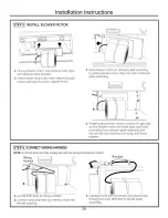
Page 20: ...0 4 While holding blower motor in place lift right side so that blower motor bolt holes align with bolts protruding from damper plate assemblg and secure with lock washers and wing nuts hand tighten ISTEP 6 1CONNECTWIRING HARNESS NOTE On ZVC48 there are three routing clips and two wiring harnessesto connect Wiring harness o ooo o 1 Locate both ends of wiring harness 3 CarefullL 2 Connect wiring ha...

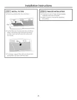
Page 21: ...ft up While maintaining slight backward pressure on filter open clip and press into place with two hands 3 To remove support filter with one hand while pulling filter clip down with the othen STEP 8 FINALIZE INSTALLATION 1 Check to be sure all tape and packaging materials have been removed 2 Refer to Owner s Manual for operating instructions 21 ...

Page 22: ...Notes 22 ...

Page 23: ...Notes 23 ...

Page 24: ... Monogram local service in your area call 1 800 444 1845 Note Product improvement is a continuing endeavor at General Electric Therefore materials appearance and specifications are subject to change without notice Monogram GEConsumer hldustrial GEAppliances GeneralElectricCompany Louisville KY40225 ge com 2006 GECompany ...

Reviews: