background image


TruVision NVR 40 unit overview 

TruVision NVR 40 User Manual 

11 

Storage  

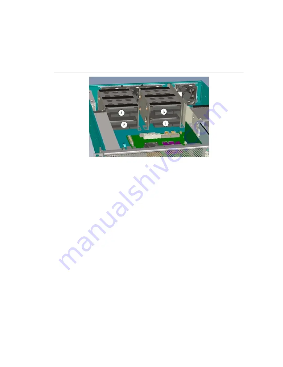
The TruVision NVR 40 network video recorder provides embedded storage. The unit 
contains two or four SATA disks (storage capacity 1 TB each) for a total storage 
capacity of 2 or 4 TB (depending on the specific model).  

Figure 5: RAID 0 mapping 


Features 

•  Two or four serial ATA disks 
•  S.M.A.R.T disk drive monitoring for reliability 
•  System status indication through LED (front panel) and alarm software 
 

Note: 

Disks are configured and presented as single storage array to the user. 


Summary of Contents for 40M06AAG

Page 1: ...GE Security P N 1069162 REV 1 0 13OCT09 TruVision NVR 40 User Manual ...

Page 2: ...device pursuant to part 15 of the FCC Rules These limits are designed to provide reasonable protection against harmful interference when the equipment is operated in a commercial environment This equipment generates uses and can radiate radio frequency energy and if not installed and used in accordance with the instruction manual may cause harmful interference to radio communications You are cauti...

Page 3: ... 8 Interface module 10 Storage 11 Hardware installation 12 Packing contents 12 Installation procedure 12 Rack mounting the unit 13 Connecting the power supply 13 Connecting the TruVision NVR 40 14 Front panel connectors 14 Interface module connectors 15 Basic setup 16 Front panel LEDs 16 Starting and configuring the TruVision NVR 40 17 Turn on the unit 17 Installing on a network 17 Access the embe...

Page 4: ...es 33 Technical specifications 34 Dimensions 34 Weight 34 AC power module 1 x 300W PSU 34 Standards and regulations 35 International standards 35 Potential for radio frequency interference 35 European regulations 35 ESD precautions 36 Safety compliance 36 EMC compliance 36 AC power cords 36 ...

Page 5: ...for installing hardware and wiring are not the ones who configure the software and administer the network therefore this publication provides information specific to installing the hardware and performing a basic system configuration To use this publication you should be familiar with electronic circuitry and wiring practices and basic network configuration and preferably have experience as an ele...

Page 6: ...wer Provide a suitable power source with electrical overload protection to meet the requirements laid down in the technical specification Equipment handling precautions Caution The RJ45 sockets are for Ethernet connection only and must not be connected to a telecommunications network Rack system safety precautions The following safety requirements must be considered when the unit is mounted in a r...

Page 7: ...rns consideration should be given to the electrical power consumption rating shown on the nameplate The electrical distribution system must provide a reliable earth for each unit and the rack The rack when configured with the units must meet the safety requirements of UL 60950 1 and IEC 60950 1 Removing the battery on the motherboard This product contains one CR2032 type single use battery When re...

Page 8: ...y equipped as follows One processor motherboard with associated memory and one 2 5 system disk Two or four SATA disks for storage 1 TB each One extension module RS 422 RS 485 serial communication and digital I O Note If you are using the device within a GE NAV environment go to the following site to get the latest version of the software http www gesecurity com portal site GESecurity menuitem 1162...

Page 9: ...ision NVR 40 is the storage part of an IP video security system which includes One Video security application software GE NAV 3 0 or later VSC 4 2 1 or later SDK based application Storage device TruVision NVR 40 Video acquisition devices Ultraview UVE 101 also know as Discovery 105E Supported IP cameras IP Cameras Integration Manual Software requirements The TruVision NVR 40 software system consis...

Page 10: ...n NVR 40 References and related documentation Centralized Configuration Server user manual VisioWave Security Center user manual TruVision NVR 40 network video recorder Figure 1 TruVision NVR 40 unit Physical description The TruVision NVR 40 unit is a 2U high enclosure for 19 rack mounting TruVision NVR 40 front panel Figure 2 TruVision NVR 40 front panel The TruVision NVR 40 unit has all its conn...

Page 11: ...ch side of the unit also make it possible to rack mount the chassis See section Rack mounting the on page 13 TruVision NVR 40 rear panel The rear panel of the TruVision NVR 40 only contains the fans and has no connectors This design is user friendly because equipment is rack mounted and therefore difficult to reach from the rear panel Moreover the cooling fans can directly pump air up through the ...

Page 12: ...lt Serial ports have been ESD protected The differential drivers receivers used MAX3089E offers the following characteristics Fail safe Receiver RS 422 RS 485 electrical compatibility Enhanced electrostatic discharge protection Selectable between half and full duplex operation Transistor I Os The 4 general purpose inputs are pulled up to high level and trigger when the circuit is closed to the gro...

Page 13: ...our SATA disks storage capacity 1 TB each for a total storage capacity of 2 or 4 TB depending on the specific model Figure 5 RAID 0 mapping Features Two or four serial ATA disks S M A R T disk drive monitoring for reliability System status indication through LED front panel and alarm software Note Disks are configured and presented as single storage array to the user ...

Page 14: ...aution Make sure that the unit is turned off before proceeding Installing handles 1 Lift the unit safely out of the packing container As you unpack the unit check for signs of shipping damage damaged box scratches dents etc If the unit is damaged or fails to meet specifications notify the VisioWave support department or your local representative immediately Also notify the carrier Retain the shipp...

Page 15: ...revent injury grasp the unit underneath the lower edge and lift with both hands To prevent injury keep your back straight and lift with your legs not your back Connecting the power supply 1 Connect the power cable to the power supply input which is situated on the front of the unit See Figure 9 en page 16 2 Connect the opposite end of the power cable to an appropriate power source The input power ...

Page 16: ... 3 Keyboard and mouse 4 Power button 5 VGA 6 LEDs 7 USB ports 8 Ethernet ports All connectors are located on the front panel of the chassis see Figure 7 above The NVR 40 unit contains the following connectors One keyboard connector purple and one mouse connector green Four high speed USB 2 0 ports One VGA Two Ethernet ports 10 100 1000 Mbps One On Off button One power plug Interface module ...

Page 17: ...t to right when facing the interface module Figure 8 The Interface module connector and pin position The detailed specifications for the module s pins are shown in Table 1 Table 1 Module pin description Serial I O 485IO UM 1 Signal Pin VCC5V 14 N C 13 GND 12 RXD1 11 RXD1 10 TXD1 9 TXD1 8 GND 7 GPI2I 6 GPI22 5 GPI23 4 GPI24 3 GPO21 2 GPO22 1 Note For GE NAV only the four alarm inputs are configurab...

Page 18: ... ready to configure the TruVision NVR 40 through its Web server using a host computer See Figure 11 on page 18 Figure 9 NVR 40 basic setup connections Front panel LEDs There are 3 different LED indicators on the front panel of the unit Figure 10 Front panel LEDs Table 2 Front panel LEDs Icon LED Description Power status This LED indicates when the unit is turned on Constant green indicates power o...

Page 19: ...an Ethernet network This involves assigning it an IP address either manually or via an automated network service DHCP Depending on your network select one of the following procedures Automatic configuration using DHCP see Network configuration on page 23 Manual configuration using fixed IP address see Network configuration on page 23 Note The TruVision NVR 40 has the default IP address 192 168 1 2...

Page 20: ...ision NVR 40 seen after connecting to the Web server Figure 11 Embedded Web server homepage On the homepage menu four options are available these menu options are also available in other widows Home return to homepage Monitoring used for monitoring the health of the unit Administration used for logon network configuration and setting changing access rights Restart used for restarting the device fo...

Page 21: ... the Monitoring option from the main menu to check Health Metrics System Configuration Video Ports Network Interfaces Health Metrics The health metric window see Figure 12 below contains information about CPU Temperature CPU Fan Speed Core Voltage 3 3 V 5 V 12 V System Date Time Uptime Figure 12 Health metric window ...

Page 22: ...ion NVR 40 20 TruVision NVR 40 User Manual System Configuration The system configuration window see Figure 13 below contains information about Equipment name Serial number Software version Figure 13 System configuration monitoring window ...

Page 23: ...sion NVR 40 TruVision NVR 40 User Manual 21 Video Ports The video ports window see Figure 14 below contains information about Slot number Port number Direction Label TCP Port Format Size FPS Bandwidth Status Figure 14 Video ports window ...

Page 24: ...R 40 User Manual Network interfaces The network interfaces window see Figure 15 below contains information about Connection Type IP Mask Cable Status Rx Tx Packets Rx Tx Errors MAC Address Default Gateway Ethernet Configuration Figure 15 Network interfaces window ...

Page 25: ...dmin Four options in the administration menu are available Network configuration Manually set system date and time Change administrative password File firmware update Configuration download Network configuration To set the network configuration follow the procedure below 1 Connect to the NVR 40 unit using a Web server Use the default IP address 192 168 1 2 Mask 255 255 0 0 See Access the embedded ...

Page 26: ...HCP select the DHCP Auto Configuration of IP Address box DHCP is NOT set as default To set static IP address fill in the available fields IP Address Network Mask Broadcast Address and Gateway Address 5 Click the Apply button at the bottom of the window to confirm the configuration Manually set system date and time To manually set system date and time enter required data in the fields below Enter n...

Page 27: ...ual 25 Change administrative password To change administrative password enter old password enter new password and confirm new password default login and password is admin admin Then press Change administrative password button Figure 18 Change administrative password window ...

Page 28: ...figuring the TruVision NVR 40 26 TruVision NVR 40 User Manual File firmware update To update the firmware browse for the file you want to load and press the upload firmware file button Figure 19 Update firmware window ...

Page 29: ...figuring the TruVision NVR 40 TruVision NVR 40 User Manual 27 Configuration download Use the Save the configuration button to save the configuration file to the designated place Figure 20 Configuration download window ...

Page 30: ...R 40 28 TruVision NVR 40 User Manual Restart the TruVision NVR 40 Select the Restart option from the main menu to restart the unit and reset with new configuration settings Use the OK button to confirm the restart Figure 21 Restart unit window ...

Page 31: ...ng There is a risk of explosion if the battery is replaced by an incorrect type 1 Turn off the unit s power switch and unplug the power supply cable from its power source 2 Turn off all accessories connected to the unit 3 Remove the cover from the TruVision NVR 40 unit 4 Remove the battery from its socket See Figure 22 5 Install a new battery into this socket Figure 22 Removing the battery Note Fo...

Page 32: ...ective cover and the user can insert the fingers in the fans by accident you must wait until the fans have stopped completely Figure 23 Rear panel with cooling fans 2 The four fans are mounted at the rear of the chassis Unscrew the cover bolts on the fan you need to replace 3 Pull out the fan you need to replace 4 Unplug the fan s cable Figure 24 Rear panel with cooling fans 5 Replace the failed f...

Page 33: ... a small physical area and operating at high speed LED Light Emitting Diode RAID Redundant Array of Independent Disks SATA Serial ATA is a serial link i e a single cable with a minimum of four wires creating a point to point connection between devices SMART Self Monitoring Analysis and Reporting Technology an open standard for developing disk drives and software systems that automatically monitor ...

Page 34: ...T 888 GE Security 888 437 3287 Toll free in the US Puerto Rico and Canada 503 885 5700 outside the toll free area F 888 329 0332 Tualatin tech support 561 998 6232 Boca Raton tech support E nstechsrv ge com gesecurity customerservice ge com T 1 305 593 4301 F 1 305 593 4300 E InfraSec TechnicalServicesLatinAmerica ge com InfraSecCustomerService LatinAmerica ge com Australia New Zealand Europe Midd...

Page 35: ...al supplier Training To view any available online training for GE Security products select the Training link Online training is not available for all products Warranty and terms information From the Customer Support menu select Return and Warranty Policy Statement or Terms and Conditions Policy Statement Customer service and technical support From the Customer Support menu select Customer Service ...

Page 36: ...3 19 01 Width across body of the unit 449 17 68 Depth from rack posts to maximum extremity of the unit 495 19 5 Weight Maximum configuration 18 kg 40 lb AC power module 1 x 300W PSU Voltage range 100 to 240 VAC Rated Voltage range selection Full Range PSU Frequency 50 60 Hz Input current 6 A Power factor correction 95 110 V 50 load Harmonics Meets EN61000 3 2 class B ...

Page 37: ... equipment in a residential area is likely to cause harmful interference in which case the user will be required to correct the interference at own expense Properly shielded and grounded cables and connectors must be used in order to meet FCC emission limits The supplier is not responsible for any radio or television interference caused by using other than recommended cables and connectors or by u...

Page 38: ...cted emissions limit levels CFR47 Part 15B Class A EN55022 Class A CISPR Class A Radiated emissions limit levels CFR47 Part 15B Class A EN55022 Class A CISPR Class A Harmonics and flicker EN61000 3 2 3 Immunity limit levels EN55024 Note The cable must not have a connection to a common ground earth point AC power cords United States Must be NRTL LISTED National Recognized Test Laboratory e g UL Cor...

Page 39: ...rope others General requirements Cord type Harmonized H05 VVF 3G1 0 Socket IEC 320 C 13 250 V 10 A Caution The Plug and the complete power cord assembly must meet the standards appropriate to the country and must have safety approvals acceptable in that country ...

Reviews: