Modifications reserved
Page 58/71
OPM_SGS_USM_M75_M75_2US_V010.doc
User Manual
SG Series 750 UL S2 & SG Series 750 T12 UL S2
7.2.2 Parallel System shutdown with Load transfer on External Maintenance Bypass
(option)
NOTE !
Not following this procedure can cause protected loads to shut down!
Never close or open either
UPS Output Switch Q1
and
External Maintenance Bypass
Switch
(option) with the
Inverter
running!
Initial situation: the
Load
is powered by all
Inverters
of the
Parallel System
.
If
eBoost™
option is available, make sure that
eBoost™ Operation Mode
is disabled
before starting the shutdown procedure.
The complete
UPS Parallel System
has to be turned OFF, while providing the
Load
power by
Utility
through a single
External Maintenance Bypass
(option).
With the
UPS Parallel System
in normal operation and the
Inverters
supplying the
Load
,
the
UPS Output
Switches Q1
,
Input Circuit Breakers CB4
and the
Battery Bank Breakers
are closed (Pos. I)
and the
External Maintenance Bypass Switch
(option) is open (Pos. O)
.
The
Synoptic Diagram
, on all UPS units, must display the
status
“
LOAD SUPPLIED BY INVERTER
”
.
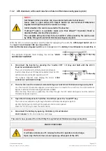
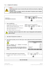
1. Disconnect the Inverter by pressing the “Inverter OFF” ( O ) key on all Units, and hold until the
LED 5 (Inverter available) turns OFF
At no redundancy, the system will transfer to
Utility
supply.
LED 5 (Inverter available)
is Off
LEDs Alarm
are lit and the
LEDs Operation
are Off.
The
Synoptic Diagram
, on all UPS units, must display the
status
“
LOAD SUPPLIED BY AUTOMATIC BYPASS
”
.
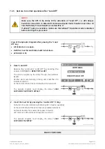
2. Transfer the Load from Internal Automatic Bypass to External Maintenance Bypass (option).
Use the
External Maintenance Bypass panel instructions
to transfer the
Load
from the
UPS
to
External
Maintenance Bypass Breaker (MBB)
.
After this step, the
Load
is supplied by the
Utility
through the
UPS Automatic Bypass
of all units and single
External Maintenance Bypass (option)
.
3. Open the UPS Output Switch Q1 (Pos. O) on all UPS units.
The
Load
is now supplied only through the
External Maintenance Bypass
.
Continue
►


