Modifications reserved
Page 66/71
OPM_SGS_USM_M75_M75_2US_V010.doc
User Manual
SG Series 750 UL S2 & SG Series 750 T12 UL S2
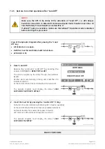
3 Insert the Inverter by pressing the
“
Inverter ON
”
( I ) key on first unit.
Soft-start of
Inverter
, indicated with blinking
LED 5 (Inverter available)
.
At the end of Soft-start the
LED 5 (Inverter available)
remains lit.
In case of sufficient output power, the output will transfer to
Inverter
.
Synoptic Diagram of first unit
Synoptic Diagram of other units
4. Insert the Inverter by pressing the
“
Inverter ON
”
( I ) key on all other units.
Do not start the next
Inverter
until the sequence of the previous ends.
Soft-start of
Inverter
, indicated with blinking
LED 5 (Inverter available)
.
At the end of Soft-start the
LED 5 (Inverter available)
remains lit.
As soon as the output power of the
Inverters
is sufficient to supply the
Load
, the output of the units with
running
Inverter
will transfer to
Inverter
.
LED Alarm
turn Off and the
LED Operation
must be lit.
The
Synoptic Diagram
, on all UPS units, must display the status
“
LOAD SUPPLIED BY INVERTER
”
.
Synoptic Diagram of first unit
Synoptic Diagram of other units
END OF PROCEDURE


