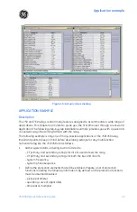
Application example
750/760 Quick Reference Guide
43
1.
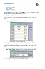
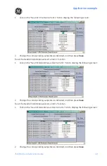
The digital inputs should be re-named. Changing the default names to meaningful
names is strongly recommended so they can be easily identified in the LCD and in
event reports.
2.
The asserted logic must be identified.
3.
The functionality of the logic inputs must be defined. Note that a logic input can be
utilized for more then one application.
If step 3 is not done, the relay will not perform any function, even if the logic input is defined
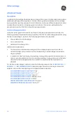
and the asserted logic is met. The last two steps use the following setpoints pages:
•
S3 LOGIC INPUTS
ZV
BREAKER FUNCTIONS
for breaker status.
•
S3 LOGIC INPUTS
ZV
CONTROL FUNCTIONS
for local/remote operations, cold load
pick up, and setpoint group changes.
•
S3 LOGIC INPUTS
ZV
USER INPUTS
to energize output relays adding time delay.
•
S3 LOGIC INPUTS
ZV
BLOCK FUNCTION
to block protection functions other than
overcurrent functions
•
S3 LOGIC INPUTS
ZV
BLOCK OC FUNCTIONS
to block overcurrent functions.
•
S3 LOGIC INPUTS
ZV
TRANSFER FUNCTIONS
to set inputs that will work with the
automatic transfer scheme.
•
S3 LOGIC INPUTS
ZV
RECLOSER FUNCTIONS
(760 relay only) to set inputs to work
with the autorecloser functions.
•
S3 LOGIC INPUTS
ZV
MISC FUNCTIONS
to trigger oscillography, fault simulation, and
start demand intervals.
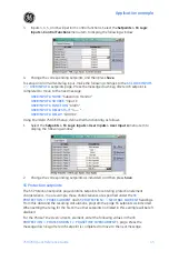
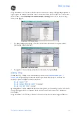
For breaker position monitoring, enter the following values in the
S3 LOGIC INPUTS
Z
LOGIC INPUTS SETUP
page:
INPUT 2 NAME
: “Brkr Position (52b)”
INPUT 2 ASSERTED LOGIC
: “Contact Close”
Then, to define the functionality of the logic input, enter the following value in the
S3 LOGIC
INPUTS
ZV
BREAKER FUNCTIONS
setpoint page:
52B CONTACT
: “Input 2”
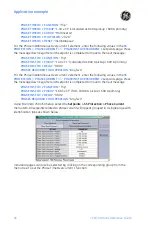
For the Remote Open/Close and Reset RTU contacts, enter the following values in the
S3
LOGIC INPUTS
Z
LOGIC INPUTS SETUP
setpoints page to define the logic inputs. Using the
message keys, find the appropriate logic name message and then define the logic input
asserted logic to complete the logic input definition as follows:
INPUT 3 NAME
: “Local Mode”
INPUT 3 ASSERTED LOGIC
: “Contact Close”
INPUT 4 NAME
: “Remote Open”
INPUT 4 ASSERTED LOGIC
: “Contact Close”
INPUT 5 NAME
: “Remote Close”
INPUT 5 ASSERTED LOGIC
: “Contact Close”
INPUT 6 NAME
: “Reset”
INPUT 6 ASSERTED LOGIC
: “Contact Close”
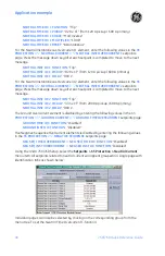
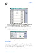
Once the Logic Input definitions are completed, it is necessary to define their functionality
by entering the following values in the
S3 LOGIC INPUTS
ZV
CONTROL FUNCTIONS
setpoint page. Using the message keys, locate the appropriate logic function and select the
corresponding logic input to perform the function.
Summary of Contents for 750
Page 2: ......
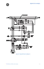
Page 39: ...Application example 750 760 Quick Reference Guide 35 Figure 17 Typical three line diagram...
Page 41: ...Application example 750 760 Quick Reference Guide 37 Figure 19 Typical control diagram...
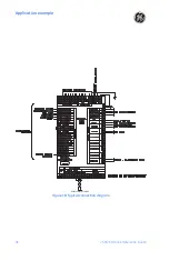
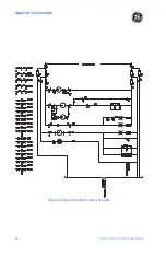
Page 42: ...Application example 38 750 760 Quick Reference Guide Figure 20 Typical breaker control diagram...
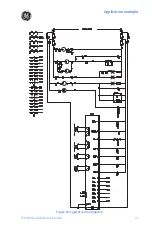
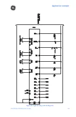
Page 43: ...Application example 750 760 Quick Reference Guide 39 Figure 21 Typical relay control diagram...

