Other settings
50
750/760 Quick Reference Guide
OTHER SETTINGS
Description
In addition to the settings illustrated above, there will be cases in feeder applications where
additional settings will be required, to monitor other system parameters such as voltage
levels, generate auxiliary outputs for local indication, and to use different setpoints in order
to adapt the protection to changing system conditions. This section will illustrate the
procedures to set the 750/760 to meet those requirements.
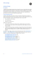
Undervoltage protection
Using the same system information as shown in the previous application example, the
following example illustrates the steps to set the 750/760 for undervoltage protection using
the Bus Undervoltage 1 element. The following parameters are provided:
•
Pickup: 80% of nominal voltage
•
Curve: definite time
•
Additional time delay: 10.0 s
Additional Considerations:
•
The line will be considered de-energized if the voltage drops to less than 10% of
nominal voltage. A trip condition will be initiated only if undervoltage is detected in
any two phases.
•
In addition to the Trip 1 Relay, the Auxiliary 3 relay will be used as local indication. In
order to provide additional circuit monitoring, Auxiliary 3 relay will be set as Fail Safe,
and shall remain energized after the condition is cleared and the reset button is
pressed.
For the Bus Undervoltage 1 element, enter the following values in the
S5 PROTECTON
ZV
VOLTAGE
ZV
BUS UNDERVOLTAGE 1
setpoints page. Press the enter key to save each
setpoint, and use the message keys to navigate between setpoints.
BUS UNDERVOLTAGE 1 FUNCTION
: “Trip”
BUS UNDERVOLTAGE 1 RELAYS (3-7)
: “3----”
BUS UNDERVOLTAGE 1 PICKUP
: “0.8 x VT”
BUS UNDERVOLTAGE 1 CURVE
: “Definite Time”
BUS UNDERVOLTAGE 1 DELAY
: “10.00 s”
PHASES REQUIRED FOR OPERATION
: “Any Two”
MINIMUM OPERATING VOLTAGE
: “0.10 x VT”
Summary of Contents for 750
Page 2: ......
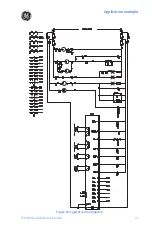
Page 39: ...Application example 750 760 Quick Reference Guide 35 Figure 17 Typical three line diagram...
Page 41: ...Application example 750 760 Quick Reference Guide 37 Figure 19 Typical control diagram...
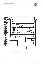
Page 42: ...Application example 38 750 760 Quick Reference Guide Figure 20 Typical breaker control diagram...
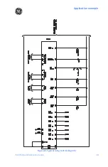
Page 43: ...Application example 750 760 Quick Reference Guide 39 Figure 21 Typical relay control diagram...

