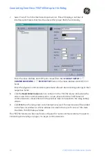
Connecting EnerVista 750/760 Setup to the Relay
750/760 Quick Reference Guide
15
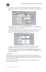
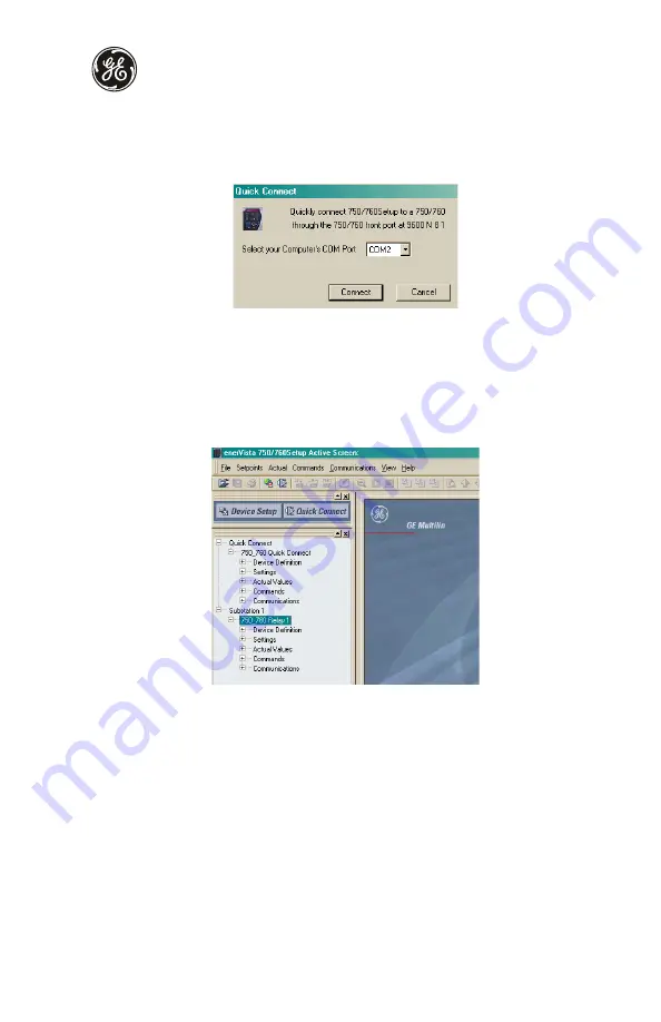
Using the Quick Connect feature
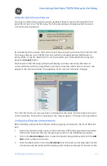
The Quick Connect button can be used to establish a fast connection through the front
panel RS232 port of a 750/760 relay. The following window will appear when the Quick
Connect button is pressed:
As indicated by the window, the Quick Connect feature quickly connects the EnerVista 750/
760 Setup software to a 750/760 front port with the following settings: 9600 baud, no
parity, 8 bits, 1 stop bit. Select the PC communications port connected to the relay and
press the
Connect
button.
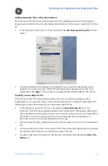
The EnerVista 750/760 Setup software will display a window indicating the status of
communications with the relay. When connected, a new Site called “Quick Connect” will
appear in the Site List window.
The properties of this new site cannot be changed
.
The 750/760 Site Device has now been configured via the Quick Connect feature for serial
communications. Proceed to
on page 17 to begin communications.
Configuring Ethernet communications
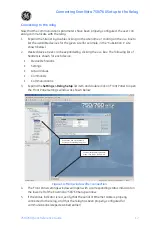
Before starting, verify that the Ethernet cable is properly connected to the RJ-45 Ethernet
port.
1.
Install and start the latest version of the EnerVista 750/760 Setup software (available
from the GE EnerVista CD). See the previous section for the installation procedure.
2.
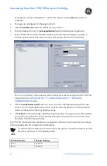
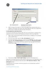
Click on the
Device Setup
button to open the Device Setup window and click the
Add
Site
button to define a new site.
3.
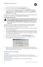
Enter the desired site name in the
Site Name
field. If desired, a short description of site
can also be entered along with the display order of devices defined for the site. In this
Summary of Contents for 750
Page 2: ......
Page 39: ...Application example 750 760 Quick Reference Guide 35 Figure 17 Typical three line diagram...
Page 41: ...Application example 750 760 Quick Reference Guide 37 Figure 19 Typical control diagram...
Page 42: ...Application example 38 750 760 Quick Reference Guide Figure 20 Typical breaker control diagram...
Page 43: ...Application example 750 760 Quick Reference Guide 39 Figure 21 Typical relay control diagram...


