Advanced EnerVista 750/760 Setup features
26
750/760 Quick Reference Guide
8.
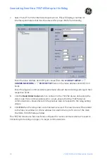
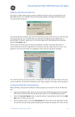
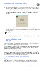
The EnerVista 750/760 Setup software now prepares the 750/760 to receive the new
firmware file. The 750/760 will display a message indicating that it is in Upload Mode.
While the file is being loaded into the 750/760, a status box appears showing how
much of the new firmware file has been transferred and how much is remaining, as
well as the upgrade status. The entire transfer process takes approximately five
minutes.
9.
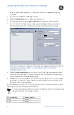
The EnerVista 750/760 Setup software will notify the user when the 750/760 has
finished loading the file. Carefully read any displayed messages and click
OK
to return
the main screen.
Cycling power to the relay is recommended after a firmware upgrade.
After successfully updating the 750/760 firmware, the relay will not be in service and will
require setpoint programming. To communicate with the relay, the following settings will
have to me manually programmed.
MODBUS COMMUNICATION ADDRESS
BAUD RATE
PARITY
(if applicable)
When communications is established, the saved setpoints must be reloaded back into the
relay. See
Loading setpoints from a file
on page 24 for details.
Modbus addresses assigned to firmware modules, features, settings, and corresponding
data items (i.e. default values, min/max values, data type, and item size) may change
slightly from version to version of firmware.
The addresses are rearranged when new features are added or existing features are
enhanced or modified. The
EEPROM DATA ERROR
message displayed after upgrading/
downgrading the firmware is a resettable, self-test message intended to inform users that
the Modbus addresses have changed with the upgraded firmware. This message does not
signal any problems when appearing after firmware upgrades.
ADVANCED ENERVISTA 750/760 SETUP FEATURES
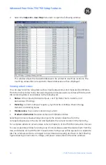
Triggered events
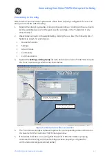
While the interface is in either on-line or off-line mode, data generated by triggered
specified parameters can be viewed and analyzed via one of the following features:
NOTE
Summary of Contents for 750
Page 2: ......
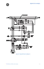
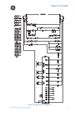
Page 39: ...Application example 750 760 Quick Reference Guide 35 Figure 17 Typical three line diagram...
Page 41: ...Application example 750 760 Quick Reference Guide 37 Figure 19 Typical control diagram...
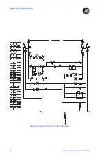
Page 42: ...Application example 38 750 760 Quick Reference Guide Figure 20 Typical breaker control diagram...
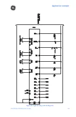
Page 43: ...Application example 750 760 Quick Reference Guide 39 Figure 21 Typical relay control diagram...


