4–50
869 MOTOR PROTECTION SYSTEM – INSTRUCTION MANUAL
DEVICE
CHAPTER 4: SETPOINTS
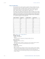
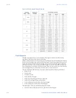
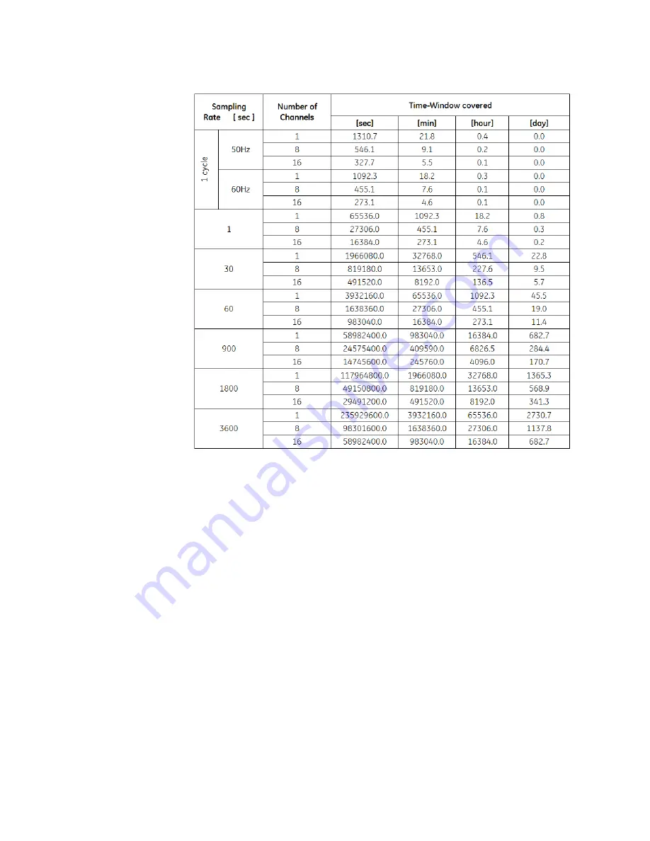
Figure 4-10: Data Logger Storage Capacity
Fault Reports
The 869 relay supports up to 15 fault reports. The trigger conditions and the analog
quantities to be stored are entered in this menu.
When enabled, this function monitors the pre-fault trigger. The pre-fault data are stored in
the memory for prospective creation of the fault report on the rising edge of the pre-fault
trigger. The element waits for the fault trigger as long as the pre-fault trigger is asserted,
but not shorter than 1 second. When the fault trigger occurs, the fault data is stored and
the complete report is created. If the fault trigger does not occur within 1 second after the
pre-fault trigger drops out, the element resets and no record is created.
The user programmable fault report contains a header with the following information:
•
Relay model
•
Device name
•
Firmware revision
•
Date and time of trigger
•
Name of pre-fault trigger (FlexLogic operand)
•
Name of Fault trigger (FlexLogic operand)
•
Active setting group at the time of pre-fault trigger
•
Active setting group at the time of fault trigger.
The fault report continues with the following information:
•
All current and voltage phasors (one cycle after the fault trigger)
Summary of Contents for 869
Page 10: ...VIII 869 MOTOR PROTECTION SYSTEM INSTRUCTION MANUAL ...
Page 127: ...CHAPTER 3 INTERFACES SOFTWARE INTERFACE 869 MOTOR PROTECTION SYSTEM INSTRUCTION MANUAL 3 49 ...
Page 129: ...CHAPTER 3 INTERFACES SOFTWARE INTERFACE 869 MOTOR PROTECTION SYSTEM INSTRUCTION MANUAL 3 51 ...
Page 538: ...4 406 869 MOTOR PROTECTION SYSTEM INSTRUCTION MANUAL TESTING CHAPTER 4 SETPOINTS ...
Page 578: ...6 22 869 MOTOR PROTECTION SYSTEM INSTRUCTION MANUAL FLEXELEMENTS CHAPTER 6 METERING ...
Page 592: ...7 14 869 MOTOR PROTECTION SYSTEM INSTRUCTION MANUAL CLEAR RECORDS CHAPTER 7 RECORDS ...

