CHAPTER 1: INTRODUCTION
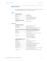
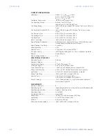
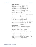
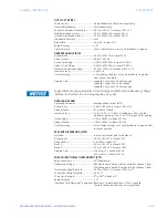
869 ORDER CODES
869 MOTOR PROTECTION SYSTEM – INSTRUCTION MANUAL
1–9
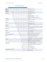
Figure 1-3: 869 Order Codes
869 E ** **
** H *
*
A
* N G *
*
*
*
*
*
*
*
* N *
Interface
869
|
|
|
|
|
|
|
|
|
|
|
|
|
|
|
|
|
|
|
|
|
|
869 Motor Protection System
Application
E
|
|
|
|
|
|
|
|
|
|
|
|
|
|
|
|
|
|
|
|
|
Standard
Phase Currents
³
Slot J Bank 1/2
P1
|
|
|
|
|
|
|
|
|
|
|
|
|
|
|
|
|
|
|
|
1A three-phase current inputs (J1)
P5
|
|
|
|
|
|
|
|
|
|
|
|
|
|
|
|
|
|
|
|
5A three-phase current inputs (J1)
Phase Currents
³
Slot K Bank 1
NN |
|
|
|
|
|
|
|
|
|
|
|
|
|
|
|
|
|
|
No phase current inputs
P1
|
|
|
|
|
|
|
|
|
|
|
|
|
|
|
|
|
|
|
1A three-phase current inputs (K1)
P5
|
|
|
|
|
|
|
|
|
|
|
|
|
|
|
|
|
|
|
5A three-phase current inputs (K1)
Ground Currents
G1 |
|
|
|
|
|
|
|
|
|
|
|
|
|
|
|
|
|
1A ground input (J1)
G5 |
|
|
|
|
|
|
|
|
|
|
|
|
|
|
|
|
|
5A ground input (J1)
B1 |
|
|
|
|
|
|
|
|
|
|
|
|
|
|
|
|
|
1A ground (J1) + 50:0.025A
(K1, included with current protection M option only)
B5 |
|
|
|
|
|
|
|
|
|
|
|
|
|
|
|
|
|
5A ground (J1) + 50:0.025A
(K1, included with current protection M option only)
0B |
|
|
|
|
|
|
|
|
|
|
|
|
|
|
|
|
|
50:0.025A (J1), only available if NN is selected for Slot K Bank 1
Power Supply
L
|
|
|
|
|
|
|
|
|
|
|
|
|
|
|
|
|
24 to 48 V DC
H
|
|
|
|
|
|
|
|
|
|
|
|
|
|
|
|
|
110 to 250 V DC/110 to 230 V AC
Slot B - LV IO
N
|
|
|
|
|
|
|
|
|
|
|
|
|
|
|
|
None
R
|
|
|
|
|
|
|
|
|
|
|
|
|
|
|
|
6 X RTDS (Pt100, Ni100, Ni120)
S
|
|
|
|
|
|
|
|
|
|
|
|
|
|
|
|
6 X RTDS (Pt100, Ni100, Ni120, Cu10)
Slot C- LV IO
N
|
|
|
|
|
|
|
|
|
|
|
|
|
|
|
None
R
|
|
|
|
|
|
|
|
|
|
|
|
|
|
|
6 X RTDS (Pt100, Ni100, Ni120)
S
|
|
|
|
|
|
|
|
|
|
|
|
|
|
|
6 X RTDS (Pt100, Ni100, Ni120, Cu10)
Slot F - HV IO
A
|
|
|
|
|
|
|
|
|
|
|
|
|
|
|
|
|
|
|
|
|
|
|
|
|
|
|
|
2 Form A (Vmon), 3 Form C, 7 Digital Inputs (Low/High Voltage, Int/Ext
Supply)
Slot G - HV IO
N
|
|
|
|
|
|
|
|
|
|
|
|
|
None
A
|
|
|
|
|
|
|
|
|
|
|
|
|
2 Form A, 3 Form C, 7 Digital Inputs (Low/High Voltage, Int/Ext Supply)
L
|
|
|
|
|
|
|
|
|
|
|
|
|
7 DcmA O/P + 4 DcmA I/P + 1 RTD
Slot H - HV IO
N
|
|
|
|
|
|
|
|
|
|
|
|
None (High Voltage I/O)
F
|
|
|
|
|
|
|
|
|
|
|
|
10 Digital 4 Arc Flash Inputs
A
|
|
|
|
|
|
|
|
|
|
|
|
2 Form A, 3 Form C, 7 Digital Inputs (Low/High Voltage, Int/Ext Supply)
Faceplate
M
|
|
|
|
|
|
|
|
|
|
|
Basic = Membrane Keypad
G
|
|
|
|
|
|
|
|
|
|
|
Standard = Rugged Keypad
Current Protection
S
|
|
|
|
|
|
|
|
|
|
Basic: 12/14, 19, 37, 38, 46, 49, 50P, 50N, 50G, 50_2, 50LR(Mechanical
Jam), 51P, 51N, 51G, 66, 86
M
|
|
|
|
|
|
|
|
|
|
Standard: Basic + 67P, 67N, 87S (2nd CT Bank required for 87S)
Voltage Monitoring and Protection
S
|
|
|
|
|
|
|
|
|
Standard: 27P, 27X, 47, 59P, 59N, 59X, 81O, 81U, VTFF
P
|
|
|
|
|
|
|
|
|
Advanced : St 32, 40, 40Q, 55, 59_2, 78
Control
B
|
|
|
|
|
|
|
|
Basic: Breaker/Contactor Control, Virtual Inputs
F
|
|
|
|
|
|
|
|
Standard: Basic + FlexLogic, 50BF, Trip Bus
T
|
|
|
|
|
|
|
|
Advanced HMI: St Tab PBs, Annunciator Panel, Configurable
SLDs with Bay Control
Monitoring
B
|
|
|
|
|
|
|
|
|
|
|
|
|
|
|
|
|
|
|
|
|
Basic: Motor Health Report, Motor Start Report, Motor Learned Data,
Data Logger, Breakers Coil Monitoring, Breaker Arcing, Harmonics,
THD, Demand
C
|
|
|
|
|
|
|
Standard: Basic + Breaker Health Report, Broken Rotor Bar
A
|
|
|
|
|
|
|
Advanced: St Harmonic Detection, Stator Inter-turn Fault
E
|
|
|
|
|
|
|
Extended: Ad ESA Functions
Communications
S
E
|
|
|
|
|
|
|
|
|
|
Standard: Front USB, 1 x Rear RS485: Modbus RTU, DNP3.0, IEC60870-
5-103 + 1 x Ethernet (Modbus TCP, DNP)
1
E
|
|
|
|
|
|
|
|
|
|
Advanced: Front USB, 1 x Rear RS485 + 2 x Ethernet Fiber, MODBUS
RTU/TCP, DNP3.0, IEC 60870-5-103/104, 1588, SNTP, OPC-UA
1 P
|
|
|
|
|
Ad PRP
2 A
|
|
|
|
|
Ad IEC 61850
2
E
|
|
|
|
|
Ad PRP + IEC 61850
3 A
|
|
|
|
|
Ad Extended IEC 61850
3
E
|
|
|
|
|
Ad PRP + Extended IEC 61850
Advanced Communications Connector
N
|
|
|
|
None
S
|
|
|
|
ST, Multi-mode 1310 nm
C
|
|
|
|
RJ45, Copper 10/100M
Summary of Contents for 869
Page 10: ...VIII 869 MOTOR PROTECTION SYSTEM INSTRUCTION MANUAL ...
Page 127: ...CHAPTER 3 INTERFACES SOFTWARE INTERFACE 869 MOTOR PROTECTION SYSTEM INSTRUCTION MANUAL 3 49 ...
Page 129: ...CHAPTER 3 INTERFACES SOFTWARE INTERFACE 869 MOTOR PROTECTION SYSTEM INSTRUCTION MANUAL 3 51 ...
Page 538: ...4 406 869 MOTOR PROTECTION SYSTEM INSTRUCTION MANUAL TESTING CHAPTER 4 SETPOINTS ...
Page 578: ...6 22 869 MOTOR PROTECTION SYSTEM INSTRUCTION MANUAL FLEXELEMENTS CHAPTER 6 METERING ...
Page 592: ...7 14 869 MOTOR PROTECTION SYSTEM INSTRUCTION MANUAL CLEAR RECORDS CHAPTER 7 RECORDS ...

