4–74
869 MOTOR PROTECTION SYSTEM – INSTRUCTION MANUAL
SYSTEM
CHAPTER 4: SETPOINTS
NUMBER OF POLES
Range: 2 to 64 in steps of 2
Default: 2
This setting represents the number of poles of the motor.
MAX. ACCELERATION TIME
Range: 1.00 to 180 s in steps of 0.01 s
Default: 10.00 s
This setting specifies the maximum acceleration time. This setting can be estimated
experimentally by starting a given motor several times under various load and electrical
conditions and measuring the starting time. Some security margin should be applied.
This setting is used by the Acceleration Time element (see Protection > Motor) and Motor
Start Statistics (see Records).
The Acceleration Time element operates if the motor is not in the Running state when
this time expires.
Regardless of whether the Acceleration Time element is Enabled or Disabled, this setting
is also required to calculate the Motor Start Statistics when the motor doesn’t go in the
Running state from the Start state, i.e. unsuccessful motor start. For a successful motor
start, motor Starting and Running states are used to calculate the motor start statistics.
2-SPEED MOTOR PROTECTION
Range: Disabled, Enabled
Default: Disabled
This setting is used to enable the two-speed motor function. This function provides
proper protection for a two-speed motor where there are two different full load values.
The two-speed functionality is required for motors having two windings wound into one
stator. One winding, when energized, provides one of the speeds. When the second
winding is energized, the motor takes on the speed determined by the second winding.
The 869 algorithm integrates the heating at each speed into one thermal model using a
common thermal capacity used register value for both speeds. Using the 869 for such
applications provides several options, allowing the removal of traditional wiring and
interlocking.
–
Use the 869 front panel pushbuttons and provide necessary operate and
interlock logic via FlexLogic.
–
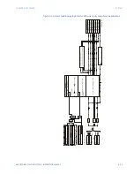
Use the external pushbuttons and provide necessary operate and interlock logic
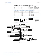
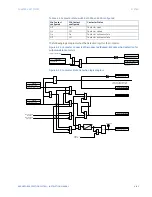
using FlexLogic as shown below.
–
Use a traditional external control schematic with some connections to the 869 for
control and protection.
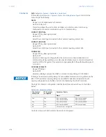
SPEED2 MOTOR SWITCH
Range: Off, any FlexLogic Operand
Default: Off
If the two-speed motor feature is used, this setting specifies a FlexLogic operand to
indicate the current motor speed. This is typically an indication that the contactor at
speed 2 is energized. When the assigned FlexLogic operand (typically a contact input
operand) is asserted, the algorithm switches to speed 2 (high speed). If the assigned
FlexLogic operand is de-asserted, the algorithm switches to speed 1 (low speed). This
allows the 869 to determine which settings must be active at any given time.
Summary of Contents for 869
Page 10: ...VIII 869 MOTOR PROTECTION SYSTEM INSTRUCTION MANUAL ...
Page 127: ...CHAPTER 3 INTERFACES SOFTWARE INTERFACE 869 MOTOR PROTECTION SYSTEM INSTRUCTION MANUAL 3 49 ...
Page 129: ...CHAPTER 3 INTERFACES SOFTWARE INTERFACE 869 MOTOR PROTECTION SYSTEM INSTRUCTION MANUAL 3 51 ...
Page 538: ...4 406 869 MOTOR PROTECTION SYSTEM INSTRUCTION MANUAL TESTING CHAPTER 4 SETPOINTS ...
Page 578: ...6 22 869 MOTOR PROTECTION SYSTEM INSTRUCTION MANUAL FLEXELEMENTS CHAPTER 6 METERING ...
Page 592: ...7 14 869 MOTOR PROTECTION SYSTEM INSTRUCTION MANUAL CLEAR RECORDS CHAPTER 7 RECORDS ...


