4–90
869 MOTOR PROTECTION SYSTEM – INSTRUCTION MANUAL
INPUTS
CHAPTER 4: SETPOINTS
Path
:
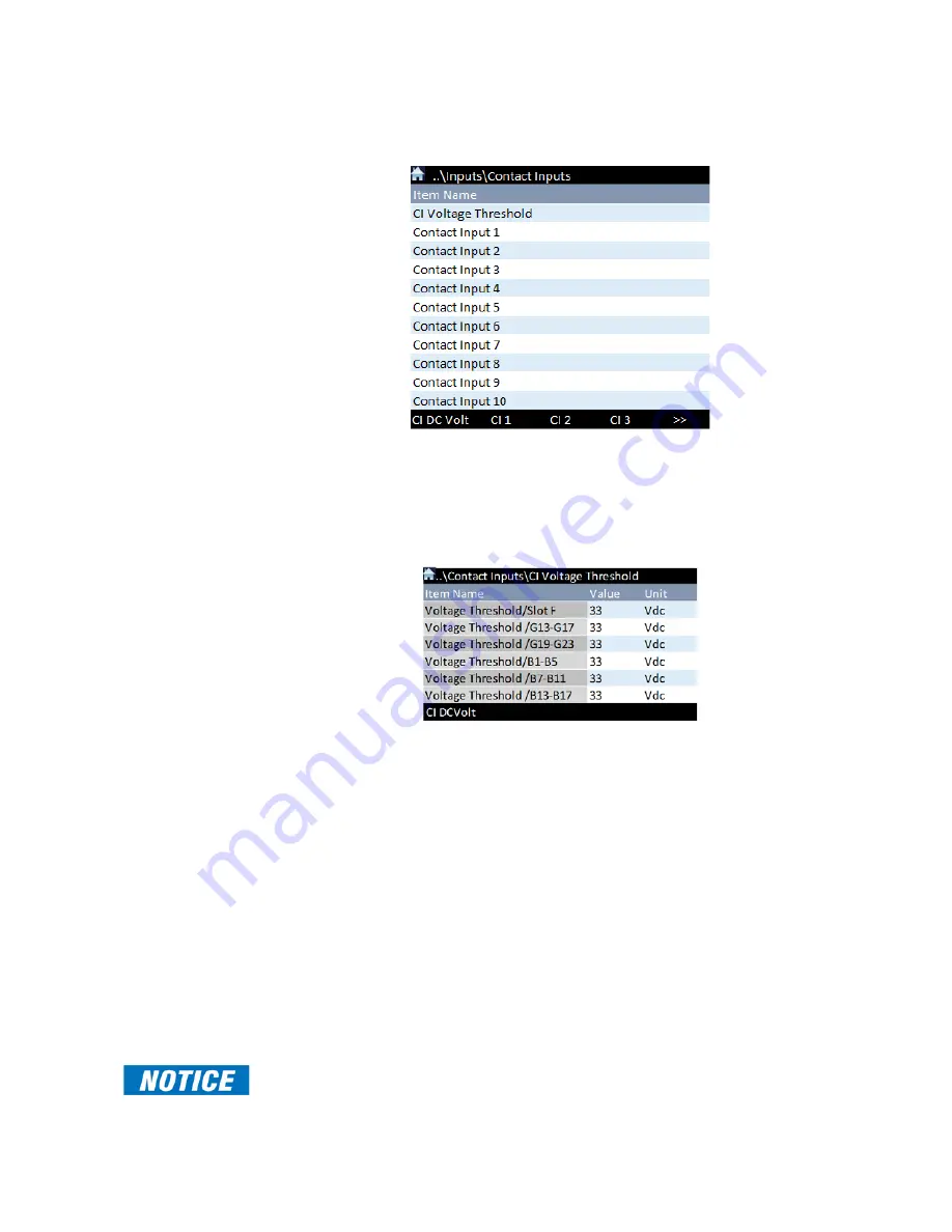
Setpoints > Inputs > Contact Inputs
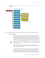
The Contact Inputs menu contains configuration settings for each Contact Input as well as
voltage threshold for all Contact Inputs.
Path
:
Setpoints > Inputs > Contact Inputs > CI Voltage Threshold
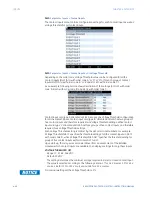
Depending on the order code, Voltage Threshold value can be configured for all the
Contact Inputs (Slot F/G/H with order code ‘A’ or ‘M’ or ‘F’) or for each group of Contact
Inputs (Slot F/G/H with order code ‘B’ or ‘K’ and Slot B/C with order code ‘C’).
As an example, following section shows description of the settings for Slot F with order
code ‘A’, Slot G with order code ‘B’ and Slot B with order code ‘C’.
Contact input card type ‘A’ allocated at Slot F requires one Voltage Threshold configuration
for all the contact inputs. Contact input card type ‘B’ allocated at Slot G has two groups of
five contact inputs and therefore requires two Voltage Threshold settings. While Contact
input card type ‘C’ allocated at Slot B has three groups of five contact inputs, and therefore
requires three Voltage Threshold settings.
Each Voltage Threshold setting is distinct by the slot or terminal numbers. For example:
‘Voltage Threshold/Slot F’ specifies the threshold setting of all the contact inputs in Slot F
with order code ‘A’; while ‘Voltage Threshold/G13-G17’ specifies the threshold setting for
group of five contact inputs with terminals G13 to G17.
Upon start-up, the relay processor determines (from an assessment of the installed
modules) which Contact Inputs are available, then displays settings for only these inputs.
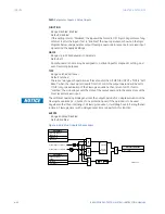
VOLTAGE THRESHOLD /[X]
Range: 17, 33, 84, 166 VDC
Default: 33 VDC
The setting determines the minimum voltage required to detect a closed Contact Input.
The value is selected according to the following criteria: 17 for 24 V sources, 33 for 48 V
sources, 84 for 110 to 125 V sources and 166 for 250 V sources.
FASTPATH:
For internal wetting set the Voltage Threshold to 17V.
Summary of Contents for 869
Page 10: ...VIII 869 MOTOR PROTECTION SYSTEM INSTRUCTION MANUAL ...
Page 127: ...CHAPTER 3 INTERFACES SOFTWARE INTERFACE 869 MOTOR PROTECTION SYSTEM INSTRUCTION MANUAL 3 49 ...
Page 129: ...CHAPTER 3 INTERFACES SOFTWARE INTERFACE 869 MOTOR PROTECTION SYSTEM INSTRUCTION MANUAL 3 51 ...
Page 538: ...4 406 869 MOTOR PROTECTION SYSTEM INSTRUCTION MANUAL TESTING CHAPTER 4 SETPOINTS ...
Page 578: ...6 22 869 MOTOR PROTECTION SYSTEM INSTRUCTION MANUAL FLEXELEMENTS CHAPTER 6 METERING ...
Page 592: ...7 14 869 MOTOR PROTECTION SYSTEM INSTRUCTION MANUAL CLEAR RECORDS CHAPTER 7 RECORDS ...


