4–116
869 MOTOR PROTECTION SYSTEM – INSTRUCTION MANUAL
PROTECTION
CHAPTER 4: SETPOINTS
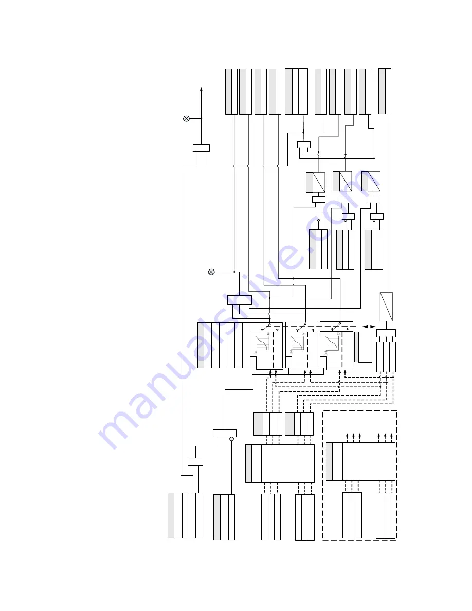
Figure 4-37: Percent Differential logic diagram
89
$
1.cdr
Ibd
–r
*
ST
AR
TING
*Ibr
>pickup
Iad
–
r*
ST
AR
TING
*Iar
>
pickup
SETPOINT
Phase
A
current
(I
a)
SETPOINT
FUNCTION
Disabled
T
rip
Pickup
AND
Phase B current
(I
b)
Phase C current
(Ic
)
RUN
TRIP
LED
:
PICKUP
OR
Neutral side currents
(I
ns
)
(K
1-
CT
) Bank
SETPOINT
BLOCK
Of
f =
0
OR
AND
Configurable
SETPOINTS
Output Relays
Do Not Operate
, Operate
LED
:
TRIP
Percent Dif
f PKP
C
FlexLogic Operands
Phase
A
current
(Ia
)
Phase B current
(Ib
)
Phase C current
(I
c)
Terminal side currents
(I
ts
)
(J
1-
CT
) Bank
I
ar
I
br
I
cr
Restraint
Phasors
I
ad
I
bd
I
cd
Dif
ferential
Phasors
Break
2
Slope
2
Slope
1
Break
1
Percent Dif
f PKP
A
FlexLogic Operands
Percent Dif
f PKP
FlexLogic Operands
Percent Dif
f PKP
B
FlexLogic Operands
Percent Dif
f OP
C
FlexLogic Operands
Percent Dif
f OP
A
FlexLogic Operands
Percent Dif
f OP
FlexLogic Operands
Percent Dif
f OP
B
FlexLogic Operands
Percent Dif
f Sat C
FlexLogic Operands
Percent Dif
f Dir C
OR
AND
Percent Dif
f Sat B
FlexLogic Operands
Percent Dif
f Dir B
OR
AND
Percent Dif
f Sat
A
FlexLogic Operands
Percent Dif
f Dir
A
OR
AND
OR
SETPOINT
TYPE
: Internal
Summation
|I
d
| =
|I
ts
–I
ns
|
|I
r
| =
MAX{|
I
ts
|, |
I
ns
|}
I
ad
>(
0.
5
x PKP
)
I
bd
>(
0.
5
x PKP
)
I
cd
>
(0
.5
x PKP
)
OR
Percent Dif
f W
arn
FlexLogic Operands
10
s
Phase
A
current
(I
a)
Phase B current
(I
b)
Phase C current
(Ic
)
Core Balance currents
(I
dcb
)
(K
1-
CT
)
Bank
Phase
A
current
(Ia
)
Phase B current
(Ib
)
Phase C current
(I
c)
Terminal side currents
(I
ts
)
(J
1-
CT
) Bank
SETPOINT
TYPE
: Core Balance
I
r
=
| I
p
|
I
d
=
| I
dcb
|
0s
Restraint
Phasors
Dif
ferential
Phasors
RUN
Icd
–
r*
ST
AR
TING
*Icr
>
pickup
RUN
T
pkp
0
T
pkp
0
T
pkp
0
SETPOINT
SETPOINT
SETPOINT
Restraint Factor Starting
(r
)
TYPE
:
Internal Summation
Core Balance
SETPOINT
Summary of Contents for 869
Page 10: ...VIII 869 MOTOR PROTECTION SYSTEM INSTRUCTION MANUAL ...
Page 127: ...CHAPTER 3 INTERFACES SOFTWARE INTERFACE 869 MOTOR PROTECTION SYSTEM INSTRUCTION MANUAL 3 49 ...
Page 129: ...CHAPTER 3 INTERFACES SOFTWARE INTERFACE 869 MOTOR PROTECTION SYSTEM INSTRUCTION MANUAL 3 51 ...
Page 538: ...4 406 869 MOTOR PROTECTION SYSTEM INSTRUCTION MANUAL TESTING CHAPTER 4 SETPOINTS ...
Page 578: ...6 22 869 MOTOR PROTECTION SYSTEM INSTRUCTION MANUAL FLEXELEMENTS CHAPTER 6 METERING ...
Page 592: ...7 14 869 MOTOR PROTECTION SYSTEM INSTRUCTION MANUAL CLEAR RECORDS CHAPTER 7 RECORDS ...

