4–130
869 MOTOR PROTECTION SYSTEM – INSTRUCTION MANUAL
PROTECTION
CHAPTER 4: SETPOINTS
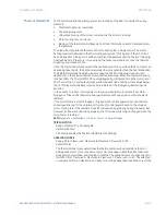
RTD BIAS VOTING BAND
Range: 0 to 50°C in steps of 1°C
Default: 10°C
This value specifies the temperature difference range between the maximum stator RTD
temperature and another voting stator RTD temperature.
Examples: Assuming RTD Bias Voting is enabled and RTD Bias Voting Band is
programmed as 10°C and three RTDs are programmed as Stator type under Monitoring
> RTD Temperature.
Example 1: Actual temperature values of RTD1, RTD2 and RTD3 are 100°C, 95°C and
80°C, respectively.
The Voting feature selects RTD1 (100°C) as the maximum temperature RTD among the
three RTDs and RTD2 (95°C) as the voting RTD. Because, temperature difference between
RTD1 and RTD2 is less than the RTD Bias Voting Band of 10°C, RTD1 temperature will be
selected as the maximum stator RTD temperature.
Example 2: Actual temperature values of RTD1, RTD2 and RTD3 are 100°C, 85°C and
80°C, respectively.
RTD1 (100°C) is selected as the maximum temperature RTD among the three RTDs and
RTD2 (85°C) as the voting RTD. Since the temperature difference between RTD1 and RTD2
is greater than the RTD Bias Voting Band of 10°C, RTD1 temperature will not be selected
as the maximum stator RTD temperature and RTD1 is declared as a malfunctioning RTD
internally.
The Voting feature will then select RTD2 (85°C) as the maximum temperature RTD from
the remaining two RTDs, and RTD3 (80°C) as the voting RTD. The RTD2 temperature (85°C)
is chosen as input to the RTD Bias feature because the temperature difference between
RTD2 and RTD3 is less than the RTD Bias Voting Band of 10°C.
VOLT. DEPENDENT (VD) FUNCTION
Range: Disabled, Enabled
Default: Disabled
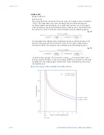
If the motor is called upon to drive a high inertia load, it is quite possible and acceptable
for the acceleration time to exceed the safe stall time (keeping in mind that a locked
rotor condition is different than an acceleration condition). The voltage dependent
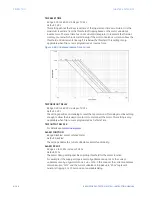
overload curve feature is tailored to protect these types of motors. This curve is
composed of the three characteristics of thermal limit curve shapes as determined by
the stall or locked rotor condition, acceleration, and running overload. The following
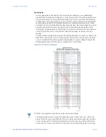
figure presents the typical thermal limit curve for high inertia application.
In this instance, each distinct portion of the thermal limit curve must be known and
protection coordinated against that curve. The relay protecting the motor must be able
to distinguish between a locked rotor condition (curve 4) and an accelerating condition
for different levels of the system voltage (curves 2 and 3). Voltage is continually
monitored during motor starting and the acceleration thermal limit portion of the relay
overload curve is dynamically adjusted based on motor voltage variations.
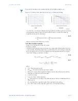
The acceleration thermal limit is a function of motor speed during the start. The
dynamically shifted voltage dependent overload curve inherently accounts for the
change in motor speed as a function of motor impedance. The change in impedance is
reflected by motor terminal voltage and line current. This method aids to set
dynamically the appropriate value of the thermal limit time for any given line current at
any given terminal voltage.
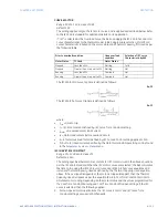
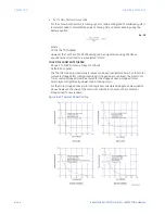
The Voltage Dependent Function setpoint enables the voltage dependent feature and
modifies the locked rotor portion of the programmed relay overload curve with respect
to the acceleration thermal limits. These thermal limits are typically available from the
machine specifications provided by motor manufacturer.
Summary of Contents for 869
Page 10: ...VIII 869 MOTOR PROTECTION SYSTEM INSTRUCTION MANUAL ...
Page 127: ...CHAPTER 3 INTERFACES SOFTWARE INTERFACE 869 MOTOR PROTECTION SYSTEM INSTRUCTION MANUAL 3 49 ...
Page 129: ...CHAPTER 3 INTERFACES SOFTWARE INTERFACE 869 MOTOR PROTECTION SYSTEM INSTRUCTION MANUAL 3 51 ...
Page 538: ...4 406 869 MOTOR PROTECTION SYSTEM INSTRUCTION MANUAL TESTING CHAPTER 4 SETPOINTS ...
Page 578: ...6 22 869 MOTOR PROTECTION SYSTEM INSTRUCTION MANUAL FLEXELEMENTS CHAPTER 6 METERING ...
Page 592: ...7 14 869 MOTOR PROTECTION SYSTEM INSTRUCTION MANUAL CLEAR RECORDS CHAPTER 7 RECORDS ...


