CHAPTER 4: SETPOINTS
PROTECTION
869 MOTOR PROTECTION SYSTEM – INSTRUCTION MANUAL
4–151
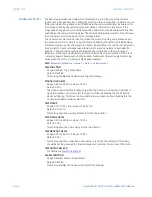
CIRCLE 1 UV SUPERVISION
Range: Disabled, Enabled
Default: Disabled
Under-voltage supervision of the element can be enabled or disabled. If Enabled for
Circle 1, the positive sequence voltage at the machine terminal should be lower than
setting value in "UV Supervision" in order to execute the Circle 1 impedance element, i.e.
LOE Circle 1 is enabled only in case voltage drops below the "UV supervision" level. This
additional check ensures the drop in generator terminal voltage in case of loss of
excitation.
CIRCLE 1 OUTPUT RELAY X
For details see
CIRCLE 2 FUNCTION
Range: Disabled, Trip, Alarm, Latched Alarm, Configurable
Default: Disabled
CIRCLE 2 DIAMETER
Range: 0.1 to 300.0 ohms in steps of 0.1 ohms
Default: 35.0 ohms
This setting is the diameter of the Circle 2 characteristic in ohms, referring to the CT/VT
secondary (relay).
CIRCLE 2 OFFSET
Range: 0.1 to 300.0 ohms in steps of 0.1 ohms
Default: 2.5 ohms
This setting is the offset of the Circle 2 characteristic in ohms, referring to the CT/VT
secondary (relay).
CIRCLE 2 PICKUP DELAY
Range: 0.00 to 600.00 s in steps of 0.01 s
Default: 1.00 s
CIRCLE 2 UV SUPERVISION
Range: Disabled, Enabled
Default: Disabled
Under-voltage supervision of the element can be enabled or disabled. If Enabled for
Circle 2, the positive sequence voltage at the machine terminal should be lower than
setting value in "UV Supervision" in order to execute the Circle 2 impedance element, i.e.
LOE Circle 1 is enabled only in case voltage drops below the "UV supervision" level. This
additional check ensures the drop in generator terminal voltage in case of loss of
excitation.
CIRCLE 2 OUTPUT RELAY X
For details see
UV SUPERVISION
Range: 0.00 to 1.50 x VT in steps of 0.01 x VT
Default: 0.70 x VT
This setting specifies the pickup value for under-voltage supervision for one or both
circles (if enabled).
BLOCK
Range: Off, Any FlexLogic operand
Default: Off
Summary of Contents for 869
Page 10: ...VIII 869 MOTOR PROTECTION SYSTEM INSTRUCTION MANUAL ...
Page 127: ...CHAPTER 3 INTERFACES SOFTWARE INTERFACE 869 MOTOR PROTECTION SYSTEM INSTRUCTION MANUAL 3 49 ...
Page 129: ...CHAPTER 3 INTERFACES SOFTWARE INTERFACE 869 MOTOR PROTECTION SYSTEM INSTRUCTION MANUAL 3 51 ...
Page 538: ...4 406 869 MOTOR PROTECTION SYSTEM INSTRUCTION MANUAL TESTING CHAPTER 4 SETPOINTS ...
Page 578: ...6 22 869 MOTOR PROTECTION SYSTEM INSTRUCTION MANUAL FLEXELEMENTS CHAPTER 6 METERING ...
Page 592: ...7 14 869 MOTOR PROTECTION SYSTEM INSTRUCTION MANUAL CLEAR RECORDS CHAPTER 7 RECORDS ...

