CHAPTER 6: METERING
MOTOR
869 MOTOR PROTECTION SYSTEM – INSTRUCTION MANUAL
6–5
Motor
Percent Differential Current
Path
:
Metering > Motor > Percent Differential
Phase A differential (Ia Diff)
Range: 0.000 to 120000.000 A
Phase B differential (Ib Diff)
Range: 0.000 to 120000.0000 A
Phase C differential (Ic Diff)
Range: 0.000 to 120000.000 A
Phase A restraint (Ia Restr)
Range: 0.000 to 120000.000 A
Phase B restraint (Ib Restr)
Range: 0.000 to 120000.000 A
Phase C restraint (Ic Restr)
Range: 0.000 to 120000.000 A
The phasors of differential and restraint currents are displayed in primary amperes.
The phasors of differential and restraint currents are displayed in primary amperes.
Motor Load
Path
:
Metering > Motor > Motor Load
MOTOR LOAD
Range: 0.00 to 40.00 x FLA in steps of 0.01 x FLA
The value represents the average of the three RMS load currents.
MOTOR CURRENT UNBALANCE
Range: 0.0 to 100.0% in steps of 0.1%
The Current Unbalance is defined as the ratio of negative-sequence to positive-
sequence current, I
2
/ I
1
when the motor is operating at a load (I
avg
) greater than FLA. If
the motor I
avg
is less than FLA, unbalance is defined as I
2
/ I
1
× I
avg
/ FLA. A full
explanation of the calculation of this value is presented for the Current Unbalance
element.
THERM MODEL BIASED LOAD
Range: 0.00 to 40.00 x FLA in steps of 0.01 x FLA
This value represents the unbalance bias motor load that shows the equivalent motor
heating current caused by the Unbalance Bias K factor.
FLTD MODEL LOAD
Range: 0.00 to 40.00 x FLA in steps of 0.01 x FLA
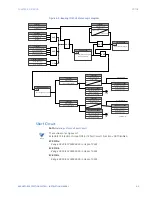
The value represents the average of the three filtered RMS load currents. The filtered
RMS load currents represent the moving average of the RMS values obtained by using
the motor load averaging filter of length equal to setpoint Motor Load Filter Interval (set
under System/Motor/Setup). Motor load averaging filter is only applicable when Motor
Load Filter Interval is set non-zero. Otherwise, this value is equal to the Motor Load. See
figure “Motor Load Averaging Filter for VFD and Cyclic Load Motor Application“.
Summary of Contents for 869
Page 10: ...VIII 869 MOTOR PROTECTION SYSTEM INSTRUCTION MANUAL ...
Page 127: ...CHAPTER 3 INTERFACES SOFTWARE INTERFACE 869 MOTOR PROTECTION SYSTEM INSTRUCTION MANUAL 3 49 ...
Page 129: ...CHAPTER 3 INTERFACES SOFTWARE INTERFACE 869 MOTOR PROTECTION SYSTEM INSTRUCTION MANUAL 3 51 ...
Page 538: ...4 406 869 MOTOR PROTECTION SYSTEM INSTRUCTION MANUAL TESTING CHAPTER 4 SETPOINTS ...
Page 578: ...6 22 869 MOTOR PROTECTION SYSTEM INSTRUCTION MANUAL FLEXELEMENTS CHAPTER 6 METERING ...
Page 592: ...7 14 869 MOTOR PROTECTION SYSTEM INSTRUCTION MANUAL CLEAR RECORDS CHAPTER 7 RECORDS ...


