background image

3

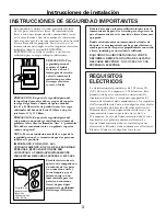
INSTRUCCIONES DE SEGURIDAD IMPORTANTES

Este producto requiere un tomacorriente eléctrico 
de tres patas conectado a tierra. El instalador debe 
llevar a cabo una inspección de continuidad a tierra 
en la caja eléctrica antes de comenzar la instalación 
para asegurar que la caja tomacorriente está conectada 
a tierra de manera apropiada. Si no lo está, o si el
tomacorriente no cumple con los requisitos eléctricos
indicados (bajo la sección REQUISITOS 
ELÉCTRICOS), se deberá recurrir a un técnico 
calificado para corregir cualquier deficiencia.

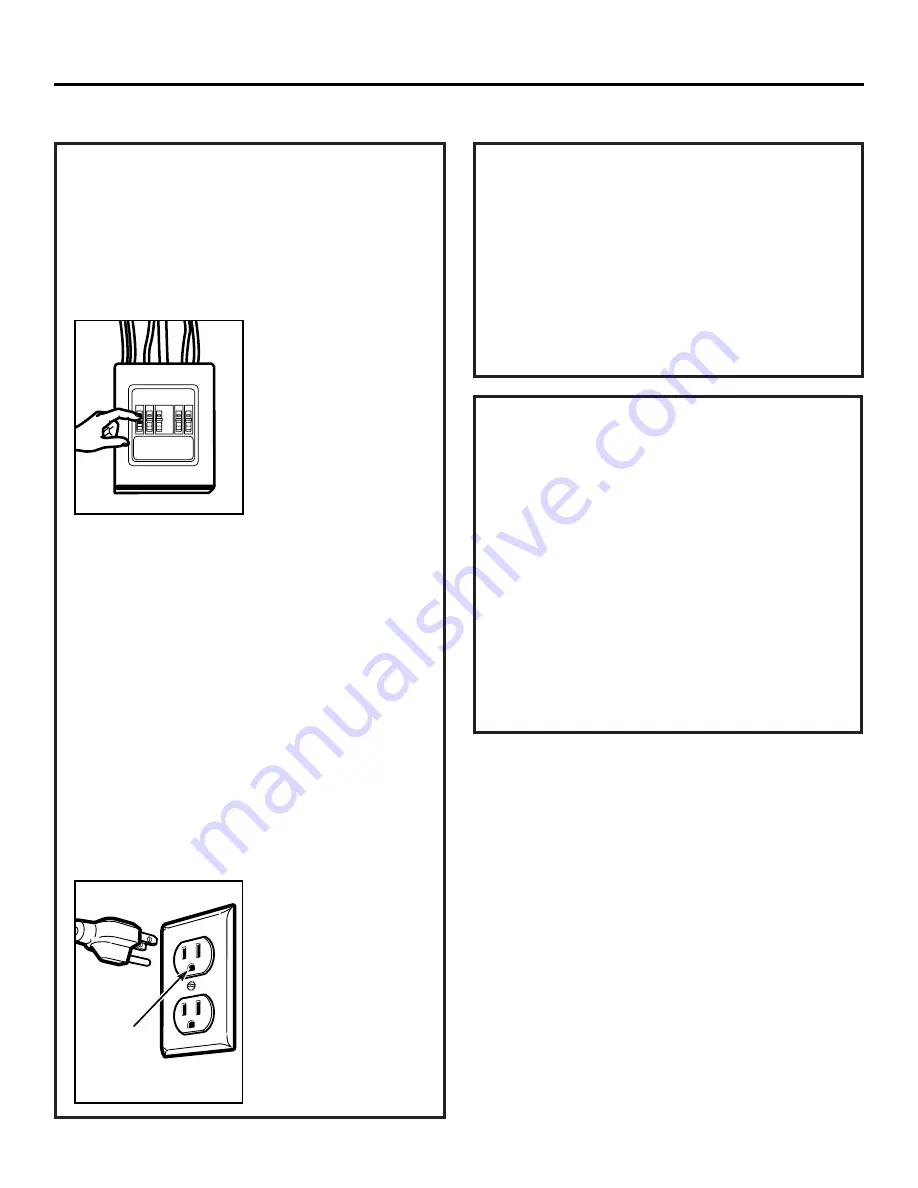
PRECAUCIÓN: Para
seguridad personal, 
remueva el fusible 
de la casa o abra el 
interruptor de circuito 
antes de comenzar la
instalación para evitar
descargas eléctricas 
severas o fatales.

PRECAUCIÓN: En pos de la seguridad personal, 
la superficie de montaje debe ser capaz de soportar 
la carga del gabinete, además del peso adicional 
(de 63 a 85 libras) de este producto, más las cargas
adicionales del horno de hasta 50 libras o un peso 
total entre 113 y 135 libras.

PRECAUCIÓN: En pos de la seguridad personal, 
este producto no puede ser instalado en sistemas de
gabinetes tales como los llamados “islas” o “penínsulas.”
Éste debe ser montado tanto a un gabinete superior 
como a una pared.

NOTA: Para una instalación más fácil y en pos de la
seguridad personal, se recomienda que dos personas
instalen este producto.
IMPORTANTE: POR FAVOR, LEA 
CUIDADOSAMENTE. EN POS DE LA SEGURIDAD
PERSONAL, ESTE APARATO DEBE SER 
CONECTADO A TIERRA APROPIADAMENTE 
PARA EVITAR DESCARGAS SEVERAS O FATALES.

El cable eléctrico de este
aparato está equipado con 
un enchufe de tres patas 
(con conexión a tierra), 
lo cual requiere que el 
mismo encaje con un
tomacorriente para tres 
patas (con conexión a 
tierra) de pared para
minimizar la posibilidad 
de descargas eléctricas.

Deberá hacer que un técnico calificado inspeccione el
tomacorriente de pared y el circuito para asegurarse de
que el tomacorriente esté conectado a tierra de manera
apropiada. 

Donde usted encuentre un tomacorriente estándar de
dos patas, es muy importante que haga que el mismo se
cambie por uno de tres patas apropiadamente conectado
a tierra, instalado por un electricista calificado.

BAJO NINGUNA CIRCUNSTANCIA NO CORTE,
DEFORME O REMUEVA NINGUNA DE LAS PATAS
DEL CABLE ELÉCTRICO. NO LO USE CON UNA
EXTENSIÓN ELÉCTRICA.

REQUISITOS
ELÉCTRICOS

La clasificación del producto es de 120 vatios CA
(AC), 60 hertz, 15 amperios y 1.58 kilovatios. Este
producto debe estar conectado a un circuito de
suministro del voltaje y frecuencia apropiados. El
tamaño del alambre debe conformarse a los requisitos
del National Electric Code o al código local en efecto
para este índice de kilovatios. El cable eléctrico de
alimentación y el interruptor deberán llevarse a un
tomacorriente único conectado a tierra de 15 a 
20 amperios. La caja del tomacorriente deberá estar
localizada en el gabinete encima del horno. La 
caja del tomacorriente debe ser instalada por un
electricista calificado y debe conformarse al National
Electrical Code o al código local en efecto.

Asegúrese de
que existe una
conexión a
tierra apropiada
antes del uso

Instrucciones de instalación

Summary of Contents for Adora Series

Page 1: ...aller Be sure to leave these instructions with the Consumer BEFORE YOU BEGIN Note to Consumer Keep these instructions for future reference Skill level Installation of this appliance requires basic mechanical and electrical skills Proper installation is the responsibility of the installer Product failure due to improper installation is not covered under the Warranty For a Spanish version of this ma...

Page 2: ...tion guide Placement of Mounting Plate 8 10 Removing the Mounting Plate 8 Finding the Wall Studs 8 Determining Wall Plate Location 9 Aligning the Wall Plate 10 Installation Types 11 22 Outside Top Exhaust 12 14 Attach Mounting Plate to Wall 12 Preparation of Top Cabinet 13 Checking for Proper Damper Operation 13 Mount the Microwave Oven 13 Adjust the Exhaust Adaptor 14 Connecting Ductwork 14 Outsi...

Page 3: ...of this appliance is equipped with a three prong grounding plug which mates with a standard three prong grounding wall receptacle to minimize the possibility of electric shock hazard from this appliance You should have the wall receptacle and circuit checked by a qualified electrician to make sure the receptacle is properly grounded Where a standard two prong wall receptacle is encountered it is v...

Page 4: ...ust care should be taken to align exhaust with space between studs or wall should be prepared at the time it is constructed by leaving enough space between the wall studs to accommodate exhaust IMPORTANT If a rectangular to round transition adaptor is used the bottom corners of the damper will have to be cut to fit using the tin snips in order to allow free movement of the damper The following cha...

Page 5: ...e installed using the most direct route and with as few elbows as possible This ensures clear venting of exhaust and helps prevent blockages Also make sure dampers swing freely and nothing is blocking the ducts Exhaust connection The hood exhaust has been designed to mate with a standard 31 4 x 10 rectangular duct If a round duct is required a rectangular to round transition adaptor must be used D...

Page 6: ...ch it was bought for repair or replacement If the unit is damaged by the customer repair or replacement is the responsibility of the customer If the unit is damaged by the installer if other than the customer repair or replacement must be made by arrangement between customer and installer DAMAGE SHIPMENT INSTALLATION PARTS INCLUDED You will find the installation hardware contained in a packet with...

Page 7: ...binets is greater than 30 a Filler Panel Kit may be used to fill in the gap between the microwave oven and the cabinets Your Owner s Manual contains the kit number for your model This microwave oven is for installation over ranges up to 36 wide If you are going to vent your microwave oven to the outside see Hood Exhaust Section for exhaust duct preparation When installing the microwave oven beneat...

Page 8: ...ve the installation instructions filters glass tray and the small hardware bag Do not remove the Styrofoam protecting the front of the oven Fold back all 4 carton flaps fully against carton sides Then carefully roll the oven and carton over onto the top side The oven should be resting in the Styrofoam REMOVING THE MICROWAVE OVEN FROM THE CARTON REMOVING THE MOUNTING PLATE FINDING THE WALL STUDS B ...

Page 9: ...nt overhang Draw a horizontal line on the back wall an equal distance below the cabinet bottom as the inside depth of the front overhang For this type of installation with front overhang only align the mounting tabs with this horizontal line not touching the cabinet bottom as described in Step D Plate position beneath flat bottom cabinet Plate position beneath recessed bottom cabinet with front ov...

Page 10: ...e marked with arrows Four holes must be used for mounting NOTE Holes C and D are inside area E If neither C nor D is in a stud find a stud somewhere in area E and draw a fifth circle to line up with the stud It is important to use at least one wood screw mounted firmly in a stud to support the weight of the microwave Set the mounting plate aside Drill holes on the circles If there is a stud drill ...

Page 11: ...led for Outside Top Exhaust except for non vented models Select the type of ventilation required for your installation and proceed to that section OUTSIDE TOP EXHAUST VERTICAL DUCT OUTSIDE BACK EXHAUST HORIZONTAL DUCT RECIRCULATING NON VENTED DUCTLESS See page 12 See page 15 See page 19 A Charcoal Filter Accessory Kit is required for the non vented exhaust See your Owner s Manual for the kit numbe...

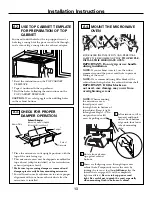
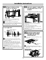
Page 12: ...s 3 A 4 ATTACH THE MOUNTING PLATE TO THE WALL A1 12 OUTSIDE TOP EXHAUST Vertical Duct Attach the plate to the wall using toggle bolts At least one wood screw must be used to attach the plate to a wall stud Remove the toggle wings from the bolts Insert the bolts into the mounting plate through the holes designated to go into drywall and reattach the toggle wings to 3 4 onto each bolt 1 INSTALLATION...

Page 13: ...l not to pinch the cord especially when mounting flush to bottom of cabinet NOTE When mounting the microwave oven thread power cord through hole in bottom of top cabinet Keep it tight throughout Steps 1 3 Do not pinch cord or lift oven by pulling cord Lift microwave tilt it forward and hook slots at back bottom edge onto four lower tabs of mounting plate Exhaust Adaptor absent on models shipped fo...

Page 14: ...n two full turns on each screw Tighten center screw completely Install grease filter See the Owner s Manual packed with the microwave Installation Instructions ADJUST THE EXHAUST ADAPTOR A5 Open the top cabinet and adjust the exhaust adaptor to connect to the house duct Back of Microwave For Front to Back or Side to Side Adjustment Slide the Exhaust Adaptor as Needed Blower Plate Damper CONNECTING...

Page 15: ...ate to Wall B4 Prepare Top Cabinet B5 Adjust Blower B6 Mount the Microwave Oven Slide exhaust adaptor to one side and remove it Back of Microwave Remove and save screw that holds blower plate to microwave Installation Instructions B 15 3 4 Damper 1 PREPARING THE REAR WALL FOR OUTSIDE BACK EXHAUST B1 You need to cut an opening in the rear wall for outside exhaust Read the instructions on the REAR W...

Page 16: ...into the mounting plate through the holes designated to go into drywall and reattach the toggle wings to 3 4 onto each bolt 1 2 Place the mounting plate against the wall and insert the toggle wings into the holes in the wall to mount the plate NOTE Before tightening toggle bolts and wood screw make sure the tabs on the mounting plate touch the bottom of the cabinet when pushed flush against the wa...

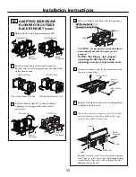
Page 17: ...n other side of the blower unit Before Rerouting After Rerouting Wires Routed Through Right Side Wires Routed Through Left Side Back of Microwave Back of Microwave Blower Plate Blower Motor Screw Secure the blower unit to the microwave with the screw from Step 1 Before Rolling After Rolling Back of Microwave End A End B Back of Microwave Back of Microwave 9 CAUTION Do not pull or stretch the blowe...

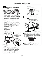
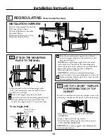
Page 18: ...ened later Be sure to keep power cord tight Be careful not to pinch the cord especially when mounting flush to bottom of cabinet NOTE When mounting the microwave oven thread power cord through hole in bottom of top cabinet Keep it tight throughout Steps 1 3 Do not pinch cord or lift oven by pulling cord Lift microwave tilt it forward and hook slots at back bottom edge onto four lower tabs of mount...

Page 19: ...s into the holes in the wall to mount the plate NOTE Before tightening toggle bolts and wood screw make sure the tabs on the mounting plate touch the bottom of the cabinet when pushed flush against the wall and that the plate is properly centered under the cabinet CAUTION Be careful to avoid pinching fingers between the back of the mounting plate and the wall Tighten all bolts Pull the plate away ...

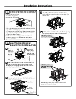
Page 20: ...ower Plate Blower Motor Screw Back of Microwave Remove and save screw that holds blower plate to microwave Lift off the blower plate and attached adaptor from the microwave NOTE Make sure wires remain routed in the grooves of the motor frame Installation Instructions BEFORE Fan Blade Openings Facing Up Damper Back of Microwave CHECK MICROWAVE ASSEMBLY C3 Exhaust Adaptor absent on models shipped fo...

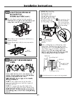
Page 21: ...e nylon grommet around the power cord hole to prevent cutting of the cord NOTE We recommend using filler blocks if the cabinet front hangs below the cabinet bottom shelf IMPORTANT If filler blocks are not used case damage may occur from overtightening screws Insert a self aligning screw through top center cabinet hole Temporarily secure the oven by turning the screw at least two full turns after t...

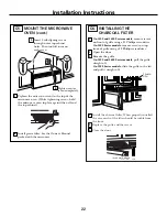
Page 22: ... on top front of grille using a 2 Phillips screwdriver Open the door Remove the grille On 1400 and 1600 Series models pull the grille straight off On 1800 Series models slide the grille to the left and pull it straight off Installation Instructions 8 7 6 Tighten the outer two screws to the top of the microwave oven While tightening screws hold the microwave oven in place against the wall and the t...

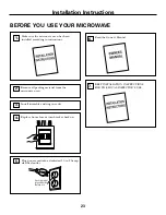
Page 23: ...the Owner s Manual 6 Replace house fuse or turn breaker back on 4 Remove all packing material from the microwave oven 2 Make sure the microwave oven has been installed according to instructions 1 23 BEFORE YOU USE YOUR MICROWAVE Ensure proper ground exists before use Installation Instructions Install turntable and ring in cavity 3 5 ...

Page 24: ...DE68 01551D 49 40247 1 06 05 JR Printed in Malaysia ...

Page 25: ...nstrucciones con el consumidor ANTES DE EMPEZAR Nota para el consumidor Guarde estas instrucciones para futura referencia Nivel de destrezas La instalación de este aparato requiere de destrezas básicas de mecánica y electricidad La instalación apropiada es responsabilidad del instalador La falla del producto debido a una instalación inapropiada no está cubierta por la garantía Horno microondas par...

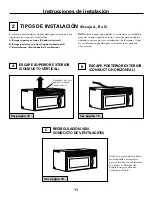
Page 26: ... montaje 8 Cómo encontrar los postes de viga en la pared 8 Cómo determinar la localización de las placas de la pared 9 Cómo alinear la placa de la pared 10 Tipos de instalación 11 22 Escape superior exterior 12 14 Cómo adherir la placa de montaje a la pared 12 Preparación del gabinete superior 13 Cómo inspeccionar si la operación del regulador de tiro es apropiada 13 Cómo montar el horno microonda...

Page 27: ...PROPIADAMENTE PARA EVITAR DESCARGAS SEVERAS O FATALES El cable eléctrico de este aparato está equipado con un enchufe de tres patas con conexión a tierra lo cual requiere que el mismo encaje con un tomacorriente para tres patas con conexión a tierra de pared para minimizar la posibilidad de descargas eléctricas Deberá hacer que un técnico calificado inspeccione el tomacorriente de pared y el circu...

Page 28: ...alinear el escape entre los espacios de los postes de viga de la pared o la pared debería ser preparada en el momento de su construcción dejando suficiente espacio entre los postes de viga de la pared para acomodar el escape IMPORTANTE Si se usa un adaptador de transición de rectángulo a redondo las esquinas del fondo del regulador de tiros deberán cortarse para que encajen usando las tijeras de c...

Page 29: ...ucto redondo es necesario se debe usar un adaptador de transición de rectangular a redondo No use un conducto menor de 6 de diámetro Longitud máxima del conducto Para lograr un movimiento satisfactorio del aire la longitud total del conducto rectangular de 31 4 x 10 o el conducto redondo de 6 de diámetro no debe sobrepasar 140 pies equivalentes Los codos transiciones paredes y tapas de techo etc p...

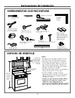
Page 30: ...ón PARTE CANTIDAD Tornillos de madera 2 1 4 x 2 Tornillos basculantes 4 y tuercas de mariposa 1 4 x 3 Tornillos de máquina 3 autoalineables 1 4 28 x 31 4 Arandela aislante de 2 nilón para gabinetes metálicos PARTES INCLUIDAS Usted encontrará los elementos de instalación en un paquete junto con la unidad Inspeccione para cerciorarse de que tiene todas las partes NOTA Se incluyen algunas partes adic...

Page 31: ...r Panel Kit podría ser necesario para rellenar las brechas entre el horno y los gabinetes Su Manual del Propietario contiene el número de kit para su modelo Este horno microondas es para ser instalado por encima de estufas hasta 36 de ancho Si usted se dispone a ventilar su horno microondas hacia el exterior ver la Sección de Campana de Escape para la preparación del conducto de escape Cuando se i...

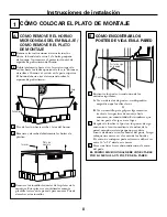
Page 32: ...emueva y deseche debidamente las bolsas de plástico 4 1 Encuentre los postes usando uno de los métodos siguientes A Use un detector de postes un dispositivo magnético que localiza clavos O B Use un martillo para golpear ligeramente a través de la superficie de montaje hasta encontrar un sonido sólido Esto indicará que hay un poste de viga en ese lugar Después de localizar el poste o los postes de ...

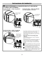
Page 33: ...race una línea horizontal en la pared posterior a una distancia debajo del fondo del gabinete igual a la profundidad interna del frente saliente Para este tipo de instalación con saliente frontal solamente alinee las orejillas de montaje con la línea horizontal sin tocar el fondo del gabinete como se describió en el Paso D Posición del plato debajo de gabinetes de fondo plano Posición del plato de...

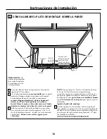
Page 34: ...je NOTA Los agujeros C y D van en el interior del área E Si ni el C ni el D están en un poste de viga encuentre un poste en algún otro lugar en el área E y marque un quinto círculo para alinearse con el poste Es importante usar por lo menos un tornillo de madera montado firmemente en un poste para apoyar el peso del horno Aparte el plato de montaje Perfore agujeros en los círculos Si hay un poste ...

Page 35: ... para modelos envìados con escape de recirculaciòn Seleccione el tipo de ventilación requerido para su instalación y proceda a tal sección ESCAPE SUPERIOR EXTERIOR CONDUCTO VERTICAL ESCAPE POSTERIOR EXTERIOR CONDUCTO HORIZONTAL RECIRCULACIÓN SIN CONDUCTO DE VENTILACIÓN Ver página 12 Ver página 15 Ver página 19 Un Kit de accesorios de filtro de carbonilla es necesario para el sistema sin ventilació...

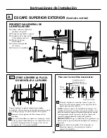
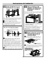
Page 36: ...TERIOR Conducto vertical Pegue el plato a la pared usando los tornillos basculantes Por lo menos un tornillo de madera debe ser usado para pegar el plato al poste de la pared Remueva las mariposas del basculante de los tornillos Inserte los tornillos en el plato de montaje a través de los agujeros diseñados para ser insertados en la pared de mampostería seca y pegue otra vez las mariposas de 3 4 e...

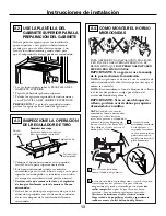
Page 37: ...use la manija de la puerta durante la instalación NOTA Si su gabinete es de metal use la arandela de nilón alrededor del cable eléctrico para evitar que el mismo sea cortado NOTA Recomendamos el uso de bloques de relleno si el frente del gabinete cuelga por debajo del estante del fondo del gabinete IMPORTANTE Si no se usan bloques de relleno podrían ocurrir daños por apretar demasiado los tornillo...

Page 38: ... a la profundidad del retroceso del gabinete Inserte 2 tornillos autoalineables a través de los agujeros exteriores superiores del horno Gire dos vueltas completas en cada tornillo Apriete el tornillo del centro completamente Instale el filtro de grasa Ver el Manual del Propietario que viene con el horno microondas Instrucciones de instalación CÓMO AJUSTAR EL ADAPTADOR DE ESCAPE A5 Abra el gabinet...
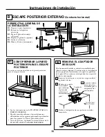
Page 39: ...N B1 Prepare la pared posterior B2 Remueva el adaptador de escape B3 Pegue el plato de montaje a la pared B4 Prepare el gabinete superior B5 Ajuste el calefactor B6 Monte el horno microondas Instrucciones de instalación B CÓMO PREPARAR LA PARED POSTERIOR PARA EL ESCAPE POSTERIOR B1 Necesita cortar una abertura en la pared posterior para el escape exterior Lea las instrucciones en la PLANTILLA PARA...
Page 40: ...r agujeros para los tornillos de apoyo superiores y un agujero suficientemente grande para que el cable eléctrico quepa Coloque el plato de montaje contra la pared e inserte las alas de mariposa en los agujeros de la pared para montar el plato NOTA Antes de apretar los tornillos basculantes y el tornillo de madera cerciórese de que las orejillas en el plato de montaje toquen el fondo del gabinete ...

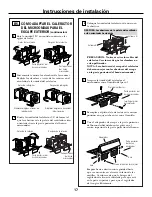
Page 41: ...ape en la parte posterior del horno microondas 4 3 CÓMO ADAPTAR EL CALEFACTOR DEL MICROONDAS PARA EL ESCAPE EXTERIOR continuación B5 Rote la unidad 180 en sentido contrario a las agujas del reloj Antes de la rotación Después de la rotación Suavemente remueva los alambres de las ranuras Redirija los alambres a través de las ranuras en el otro lado de la unidad del calefactor Antes de redirigirlos D...

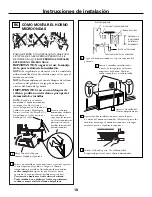
Page 42: ...mente cuando se monte al nivel del fondo del gabinete NOTA Cuando se encuentre montando el horno microondas enrosque el cable eléctrico a través del agujero en el fondo del gabinete superior Manténgalo tenso a través de los Pasos del 1 3 No pellizque el cable ni tire del horno por el cable Levante el horno microondas inclínelo hacia adelante y enganche las ranuras en el extremo inferior posterior ...

Page 43: ...lato NOTA Antes de apretar los tornillos basculantes y los tornillos de madera cerciórese de que las orejillas en el plato de montaje toquen el fondo del gabinete cuando son empujadas contra la pared y de que el plato esté centrado apropiadamente debajo del gabinete PRECAUCIÓN Tenga cuidado de evitar pellizcar sus dedos entre la parte posterior del plato de montaje y la pared Apriete todos los tor...

Page 44: ... posterior del microondas Remueva y guarde el tornillo que sostiene el motor del calefactor adherido al microondas Levante el plato del calefactor y desembrague el adaptador del microondas NOTA Cerciórese de que los alambres permanecen encaminados en las ranuras del marco del motor ANTES Las aberturas de la paleta del ventilador están orientadas hacia arriba Regulador de tiro Parte posterior del m...

Page 45: ...rir daños por apretar demasiado los tornillos 3 2 Gire el frente del horno contra el fondo del gabinete 1 Inserte un tornillo de autoalineación a través del agujero central superior del gabinete Asegure el horno temporalmente girando el tornillo por lo menos dos vueltas completas después de que las roscas hayan agarrado Luego quedarán totalmente apretadas Cerciórese de mantener el cable eléctrico ...

Page 46: ... destornillador de estrella 2 Abra la puerta Remueva la rejilla En los modelos Serie 1400 y 1600 tire de la rejilla directamente hacia afuera En los modelos Serie 1800 deslice la rejilla hacia la izquierda y tire de ella directamente hacia afuera Instrucciones de instalación 5 8 7 6 Apriete los dos tornillos exteriores hacia la parte de arriba del horno microondas Mientras aprieta los tornillos ma...
Page 47: ...0 amperios 7 Lea el Manual del Propietario 6 Reemplace el fusible de la casa o encienda de nuevo el interruptor 4 Remueva todos los materiales de embalaje del horno microondas 2 Cerciórese de que el horno ha sido instalado de acuerdo con las instrucciones 1 ANTES DE COMENZAR A USAR SU HORNO MICROONDAS Instrucciones de instalación Instale el aro rotatorio y con ruedas en la cavidad 3 5 ...
Page 48: ...DE68 01551D 49 40247 1S 06 05 JR Impreso en Malasia ...

Reviews: