background image

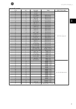
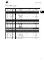
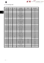
3.1.3 Analog Outputs (AO)

NPT

NPA

UNIT

DESCRIPTION

RANGED

PAR. NUMBER

AO

0

%

Bus reference

1

-200 to 200 Proportionally

mapped into the range

-32768 to 32767

-

AO

1

Bus feedback 1

Please refer to [4]

O-94

AO

2

Bus feedback 2

Please refer to [4]

O-95

AO

3

Bus feedback 3

Please refer to [4]

O-96

AO

4

Analog Output Term 42

AN-53

AO

5

Pulse Output Term 27

E-93

AO

6

Pulse Output Term 29

E-95

AO

7

GPIO Analog Output Termi-

nal X30/8

AN-63

AO

8

Analog Option Output Ter-

minal X42/7

AO-53

AO

9

Analog Option Output Ter-

minal X42/9

AO-63

AO

10

Analog Option Output Ter-

minal X42/11

AO-60

1)

 Please refer to scaling of Bus Reference and Feedback, Section on Scaling or Bus Reference and Feedbacks.

AF-600 FP Metasys

25

  3

Summary of Contents for AF-600 FP Metasys

Page 1: ...be met in connection with installation operation or maintenance Should further information be desired or should particular problems arise which are not covered sufficiently for the purchaser s purposes the matter should be referred to the GE company AF 600 FP is trademark of the General Electric Company GE Consumer Industrial 41 Woodford Avenue Plainville CT 06062 www geelectrical com drives 130R0...

Page 2: ...bout this Manual 4 References 4 2 Instructions 5 Abbreviations and Definitions 5 Network Connection 5 Hardware Set up 6 Drive Parameters 7 3 Appendix 21 Analog Inputs AI 21 Binary Inputs BI 22 Analog Outputs AO 25 Internal Integers ADI 26 Internal Floating Point ADF 27 Internal Integers ADI 30 AF 600 FP Metasys 1 ...

Page 3: ...AF 600 FP Metasys 2 1 ...

Page 4: ... is designed to be general in nature to accommodate the unique properties each device type may have Every device connection to the N2 network can be thought of as a small data manager Data points in the database are classified as analog I O floating point binary I O or integer data points floats integers or bytes Each data type has its own unique structure defined in the Metasys N2 system Protocol...

Page 5: ...ble for any costs including but not limited to those incurred as a result of lost profits or revenue loss or damage of equipment loss of computer programs loss of data the costs to substitute these or any claims by third parties GE reserves the right to revise this publication at any time and to make changes to its contents without prior notice or any obligation to notify former or present users o...

Page 6: ...CI controller NAK Not acknowledged NPA N2 Point Address Each N2 Point Type has a address range from 0 to 255 NPT N2 Point Type PAR Parameter Number 2 1 2 Network Connection Connect signal wires to terminal 68 N and terminal 69 N on main control board of the drive If shielded cabling is used connect one end of the shield to terminal 61 This terminal is connected to ground via an internal RC link It...

Page 7: ...ter use parallel connections Illustration 2 1 Network termination switch In order to avoid potential equalizing currents in the screen earth the cable screen via terminal 61 which is connected to the frame via an RC link Network termination The RS485 network must be terminated by a resistor network at both ends For this purpose set switch S801 on the control card to ON For more information see the...

Page 8: ...t value can not be changed while running Error Code 12 is issued when 1 The N2 master tries to change attribute 2 bit 6 Current State on a BO and the drive is tripped 2 The N2 master tries to change attribute 2 bit 6 Current State on a BO and the drive is trip locked except for BO 5 reset 2 1 5 Drive Parameters The following parameters may need to be manually set for each drive in the Metasys N2 n...

Page 9: ...Synch Time The internal clock is syncronized by this com mand ACK no action 8 0 Upload Optional no support in the frequency converter ACK no action 8 1 Upload Optional no support in the frequency converter ACK no action 8 3 Upload Record Optional no support in the frequency converter ACK no action 8 4 Upload Complete Optional no support in the frequency converter ACK no action 9 0 Download Optiona...

Page 10: ... 2 1 0 23 1 Byte Write Analog Input Write to Object Configuration attribute associated with each individual point ACK 2 1 0 23 8 Float Write Analog Input Write to Low Alarm Limit attrib ute associated with each individual point ACK 2 1 0 23 9 Float Write Analog Input Write to Low Warning Limit at tribute associated with each individual point ACK 2 1 0 23 10 Float Write Analog Input Write to High W...

Page 11: ...ndividual point JCI use only NAK 2 0 23 5 Float Write Analog Input 111 Write to Linear Ranging Parameter 2 attribute associated with each individual point JCI use only NAK 2 0 23 6 Float Write Analog Input 111 Write to Linear Ranging Parameter 3 attribute associated with each individual point JCI use only NAK 2 0 23 7 Float Write Analog Input 111 Write to Linear Ranging Parameter 4 attribute assoc...

Page 12: ...2 1 Byte Write Analog Output Write to Object Configuration at tribute associated with each individual point ACK 7 2 3 0 2 Float Override Analog Out put Write to analog output current value frequency setpoint ACK 7 2 3 0 2 Float Override Analog Out put Write to analog output current value frequency setpoint ACK 7 3 3 0 2 Override Release Set the current value the value that it was before the 1 Over...

Page 13: ...t 111 Object Status not writeable NAK 2 3 0 2 3 Float Write Analog Out put 111 Write to Current Value structure at tributes associated with each individual point N2 does not sup port this override function must be used NAK 2 3 0 2 4 Float Write Analog Out put 111 Write Debouncing Value in msec at tribute associated with each individual point JCI use only NAK 2 3 0 2 5 Float Write Analog Out put 11...

Page 14: ...d not be writ ten over by the network control ler Status word Warnings and Alarms ACK no action 7 7 2 0 135 Write Binary In put Optional command for slave de vices Only Attributes used for N2 commissioning purposes Not to be implemented at this time ACK no action 7 8 2 0 135 Read Binary In put Optional command for Attrib utes slave devices Only used for N2commissioningpurposes Not to be implemente...

Page 15: ...each individual point ACK no action 2 4 0 10 4 Integer Write Binary Output Write Minimum Off time attribute associated with each individual point ACK no action 2 4 0 10 5 Integer Write Binary Output Write Maximum Cycles Hour at tribute associated with each individual point ACK no action 7 7 4 0 10 Write Binary Output Optional command for slave de vices Only Attributes used for N2 commissioning pur...

Page 16: ...e 2 9 No Error Code coloumn in this table 2 1 16 Internal Floating Point Commands Acknowledged DRIVE Response Command Subcom mand Region NPA Object no Attribute No Attribute Message Type Comments ACK 1 5 0 101 1 Byte Read Internal Pa rameter of object type float Read Object Status associ ated with each individual point ACK 1 5 0 101 2 Float Read Internal Pa rameter of object type float Read Curren...

Page 17: ...t 9600 for N2 protocol par O 50 Coasting Select 3 Logic OR par O 52 DC Brake Select 3 Logic OR par O 53 Start Select 3 Logic OR par O 54 Reversing Select 0 Digital input par O 55 Set up Select 3 Logic OR par O 56 Preset Reference Select 3 Logic OR par O 94 Bus Feedback 1 0 par O 95 Bus Feedback 2 0 NB Send an F command to begin communications between the master and the drive Example 1 F command Se...

Page 18: ...e 00 Not active Checksum Y Message code XX72040400YY CR If the preceding commands were issued the drive should have accelerated to 50 after the speed reference was issued After the override release the drive should have stopped 2 2 2 Scaling of Bus Reference and Feedback Reference feedback Scaling Float IEEX hex 20 20 16384 100 3276 8 454C CCCD 50 50 16384 100 8192 4600 0000 100 100 16384 100 1638...

Page 19: ...Under voltage 0x0109 9 Inverter overloaded 0x010A 10 Motor overloaded 0x010B 11 Motor thermistor 0x010C 12 Current limit 0x020D 13 Over current Trip lock 0x020E 14 Earth fault Trip lock 0x020F 15 Switch mode fault Trip lock 0x0210 16 Short circuit Trip lock 0x0111 17 Standard bus time out 0x0112 18 HPFB time out 0x0116 22 Auto optimization not OK 0x021D 29 Heat sink temperature to high Trip lock 0...

Page 20: ...d has been issued for the drive This command can be issued through the bus or through a drive related status change or command The master can issue a series of poll commands to the network devices to get an update on any status changes from the time of the last polling When polling a frequency converter for the first time after a network has been powered up after an F command has been issued a 0 4...

Page 21: ...mal state must be programmed in the Object Configuration Attribute Attribute 1 Att XX Attribute number HA High alarm LA Low alarm HW High Warning LW Low Warning TheAICOSalarmswillonlybeclearedwhenthepointvaluegoesbelowthehighalarm warningorabovethelowalarm warninglimitbymorethantheprogrammed differential value Attribute 12 The BI COS will set the Alarm Object Status bit 4 if COS enabled Object Con...

Page 22: ...R 17 27 Analog Input GPIO X30 11 DR 75 28 Analog Input GPIO X30 12 DR 76 29 Analog Input IO option X42 1 20 000 to 20 000 LG 20 30 Analog Input IO optionX42 3 20 000 to 20 000 LG 21 31 Analog Input IO optionX42 5 20 000 to 20 000 LG 22 32 Analog Out X42 7 LG 33 33 Analog Out X42 9 LG 34 34 Analog Out X42 11 LG 35 45 Feedback 1 Unit DR 54 46 Feedback 2 Unit DR 55 47 Feedback 3 Unit DR 56 48 Ext 1 F...

Page 23: ...ing 21 26 Low Temperature 0 OK 1 Warning 22 25 Current Limit 0 OK 1 Warning 23 24 Mains Failure 0 OK 1 Warning 24 23 24V Supply Low 0 OK 1 Warning 25 22 Fieldbus Fault 0 OK 1 Warning 26 21 Speed Limit 0 OK 1 Warning 27 20 Brake IGBT 0 OK 1 Warning 28 19 Brake Resistor 0 OK 1 Warning 29 18 Brake Overload 0 OK 1 Warning 30 17 10V low 0 OK 1 Warning 31 16 Live Zero Error 0 OK 1 Warning 32 15 No Motor...

Page 24: ...Alarm 66 13 Inrush Fault 0 OK 1 Alarm 67 12 Short Circuit 0 OK 1 Alarm 68 11 DC Overvoltage 0 OK 1 Alarm 69 10 DC Undervoltage 0 OK 1 Alarm 70 9 Inverter Overload 0 OK 1 Alarm 71 8 Motor ETR Overload 0 Trip 1 Trip lock 72 7 Motor Thermal Overload 0 OK 1 Alarm 73 6 Torque Limit 0 OK 1 Alarm 74 5 Over Current 0 OK 1 Alarm 75 4 Ctrl Word Timeout 0 OK 1 Alarm 76 3 Ctrl Card Temp 0 OK 1 Alarm 77 2 Eart...

Page 25: ... function 1 reverse 114 14 Setup MSB 0 FALSE 1 TRUE 115 13 Setup LSB 0 FALSE 1 TRUE 116 12 Relay02 0 Relay04 off 1 Relay04 on 117 11 Relay01 0 Relay01 off 1 Relay01 on 118 10 Res always 0 data valid 0 FALSE 119 8 Jog 0 No Function 1 Jog 120 7 Reset 0 No Function 1 Reset 121 6 Start 0 start 1 stop 122 5 Freeze Output 0 Freeze output 1 Ramping 123 4 Q stop 0 Q stop 1 Ramping 124 3 Coast 0 Coasting 1...

Page 26: ...eedback 3 Please refer to 4 O 96 AO 4 Analog Output Term 42 AN 53 AO 5 Pulse Output Term 27 E 93 AO 6 Pulse Output Term 29 E 95 AO 7 GPIO Analog Output Termi nal X30 8 AN 63 AO 8 Analog Option Output Ter minal X42 7 AO 53 AO 9 Analog Option Output Ter minal X42 9 AO 63 AO 10 Analog Option Output Ter minal X42 11 AO 60 1 Please refer to scaling of Bus Reference and Feedback Section on Scaling or Bu...

Page 27: ... Protection F 10 31 Reference Site F 02 32 Over Volt Control B 17 33 Reference Function F 54 40 Digital Input 18 E 01 41 Digital Input 19 E 02 42 Digital Input 27 E 03 43 Digital Input 29 E 04 44 Digital Input 32 E 05 45 Digital Input 33 E 06 51 Sec Live Zero Time Out AN 00 52 Live Zero Function AN 01 53 Signal Output 42 AN 50 55 CC Relay 1 Function 0 to 255 E 24 0 56 CC Relay 2 Function 0 to 255 ...

Page 28: ...mit FMIN F 16 ADF 31 Hz Output freq high limit FMAX F 03 ADF 32 Unit Min reference RefMIN F 52 ADF 33 Unit Max reference RefMAX F 53 ADF 34 Sec Accel Time F 07 ADF 35 Sec Decel Time F 08 ADF 36 Hz Jog Frequency C 20 ADF 37 Digital Reference 1 C 05 0 ADF 38 Digital Reference 2 C 05 1 ADF 39 Digital Reference 3 C 05 2 ADF 40 Digital Reference 4 C 05 3 ADF 41 A Current Limit H 71 ADF 42 Hz Frequency ...

Page 29: ... 67 A Terminal 54 min scale mA AN 23 ADF 68 Hz Terminal 42 output puls scale E 71 ADF 69 Hz Terminal 45 output puls scale E 74 ADF 70 mSec CC Relay 1 ON Delay E 26 0 ADF 71 mSec CC Relay 1 ON Delay 0 01 to 600 00 E 27 0 ADF 72 mSec CC Relay 1 ON Delay 0 01 to 600 00 E 26 1 ADF 73 Sec CC Relay 1 ON Delay 0 01 to 600 00 E 27 1 ADF 80 Sec No Flow Timer AP 24 ADF 81 Sec Dry Pump Timer AP 27 ADF 82 Sec...

Page 30: ...ut X30 12 High Voltage 0 07 to 10 00 AN 41 ADF 124 V Analogue Input X42 1 Low Voltage 0 07 to 10 00 AO 10 ADF 125 V Analogue Input X42 1 High Voltage 0 07 to 10 00 AO 11 ADF 126 V Analogue Input X42 3 Low Voltage 0 07 to 10 00 AO 20 ADF 127 V Analogue Input X42 3 High Voltage 0 07 to 10 00 AO 21 ADF 128 V Analogue Input X42 5 Low Voltage 0 07 to 10 00 AO 30 ADF 129 V Analogue Input X42 5 High Volt...

Page 31: ...rence Site F 02 ADI 32 Over Volt Control B 17 ADI 33 Reference Function F 54 ADI 40 Digital Input 18 E 01 ADI 41 Digital Input 19 E 02 ADI 42 Digital Input 27 E 03 ADI 43 Digital Input 29 E 04 ADI 44 Digital Input 32 E 05 ADI 45 Digital Input 33 E 06 ADI 46 Reference 1 Source F 01 ADI 47 Feedback 1 Source CL 00 ADI 48 Feedback 2 Source CL 03 ADI 51 Sec Live Zero Time Out AN 00 ADI 52 Live Zero Fun...

Page 32: ...s Counter ID 07 ADI 92 Operation Mode H 03 ADI 101 Analogue Input X42 1 Mode 0 to 3 AO 00 ADI 102 Analogue Input X42 3 Mode 0 to 3 AO 01 ADI 103 Analogue Input X42 5 Mode 0 to 3 AO 02 ADI 104 Analogue Input X30 8 Mode AN 60 ADI 105 Analogue Input X42 7 mode 0 to 145 AO 50 ADI 106 Analogue Input X42 9 Mode AO 60 ADI 107 Analogue Input X42 11 Mode AO 70 ECB Bypass Mode BP 00 ADI 111 ECB Bypass Start...

Page 33: ...be met in connection with installation operation or maintenance Should further information be desired or should particular problems arise which are not covered sufficiently for the purchaser s purposes the matter should be referred to the GE company AF 600 FP is trademark of the General Electric Company GE Consumer Industrial 41 Woodford Avenue Plainville CT 06062 www geelectrical com drives 130R0...

Reviews: