


6.3.20 Secondary Pumps
Secondary pumps in a primary/secondary chilled water
pumping system are used to distribute the chilled water to
the loads from the primary production loop. The primary/
secondary pumping system is used to hydronically de-
couple one piping loop from another. In this case, the
primary pump is used to maintain a constant flow through
the chillers while allowing the secondary pumps to vary in
flow, increase control and save energy.
If the primary/secondary design concept is not used and a
variable volume system is designed, the chiller cannot
shed its load properly when the flow rate drops far
enough or too quickly. The chiller’s low evaporator
temperature safety then trips the chiller, requiring a
manual reset. This situation is common in large instal-
lations, especially when two or more chillers are installed
in parallel.
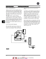
6.3.21 The AF-600 FP Solution
While the primary-secondary system with two-way valves
improves energy savings and eases system control
problems, the true energy savings and control potential is
realized by adding adjustable frequency drives.
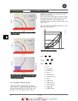
With the proper sensor location, the addition of adjustable
frequency drives allows the pumps to vary their speed to
follow the system curve instead of the pump curve.
This results in the elimination of wasted energy and
eliminates most of the over-pressurization to which two-
way valves can be subjected.
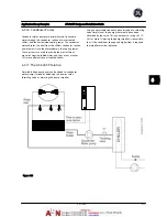
As the monitored loads are reached, the two-way valves
close down. This increases the differential pressure
measured across the load and two-way valve. As this
differential pressure starts to rise, the pump is slowed to
maintain the control head also called setpoint value. This
setpoint value is calculated by summing the pressure drop
of the load and two-way valve together under design
conditions.
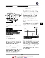
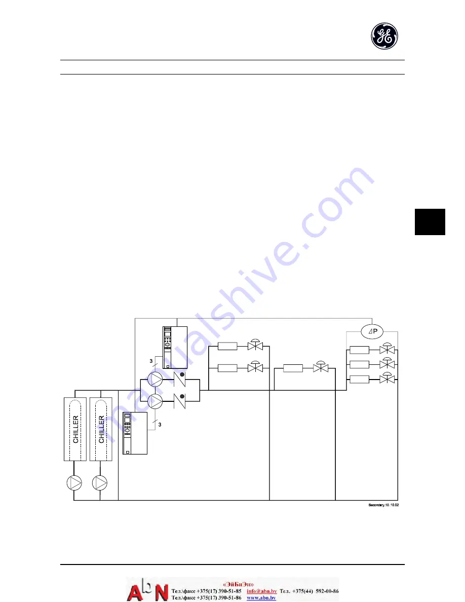
Please note that when running multiple pumps in parallel,
they must run at the same speed to maximize energy
savings, either with individual dedicated drives or one
adjustable frequency drive running multiple pumps in
parallel.
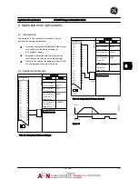
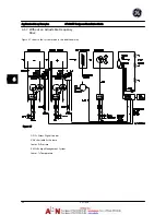
Figure 6.14
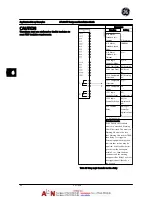
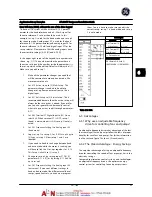
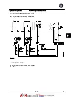
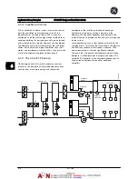
Application Set-up Examples
AF-600 FP Design and Installation Guide
DET-768A
6-15
6
6
Summary of Contents for AF-600 FP Series
Page 1: ...AF 600 FPTM Fan Pump Drive Design and Installation Guide GE ...
Page 17: ...Introduction AF 600 FP Design and Installation Guide 1 10 DET 768A 1 1 ...
Page 39: ...Start Up and Functional Tes AF 600 FP Design and Installation Guide 3 6 DET 768A 3 3 ...
Page 57: ...About Programming AF 600 FP Design and Installation Guide 5 14 DET 768A 5 5 ...
Page 73: ...Application Set up Examples AF 600 FP Design and Installation Guide 6 16 DET 768A 6 6 ...
Page 83: ...Installation Consideration AF 600 FP Design and Installation Guide 7 10 DET 768A 7 7 ...
Page 87: ...Status Messages AF 600 FP Design and Installation Guide 8 4 DET 768A 8 8 ...
Page 97: ...Warnings and Alarms AF 600 FP Design and Installation Guide 9 10 DET 768A 9 9 ...
Page 101: ...Basic Troubleshooting AF 600 FP Design and Installation Guide 10 4 DET 768A 10 0 ...
Page 103: ...Terminal and Applicable Wir AF 600 FP Design and Installation Guide 11 2 DET 768A 11 1 ...


