background image

AF-70 LP

Macro Configurations

Over

view

7

23


22


7.


Analog and Digital Input Macro Configurations 

7.1.


Overview 

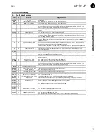
AF-70 uses a Macro approach to simplify the configuration of the Analog and Digital Inputs. There are two key parameters which determine the 

input functions and drive behaviour: 

F-12 – Selects the main drive control source and determines how the output frequency of the drive is primarily controlled. 

H-15 – Assigns the Macro function to the analog and digital inputs. 
Additional parameters can then be used to further adapt the settings, e.g. 

H-16 – Used to select the format of the analog signal to be connected to analog input 1, e.g. 0 – 10 Volt, 4 – 20mA 

H-30 – Determines whether the drive should automatically start following a power on if the Enable Input is present 

H-31 – When Keypad Mode is selected, determines at what output frequency / speed the drive should start following the enable command, and 

also whether the keypad start key must be pressed or if the Enable input alone should start the drive. 

H-47 – Used to select the format of the analog signal to be connected to analog input 2, e.g. 0 – 10 Volt, 4 – 20mA 
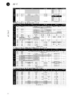
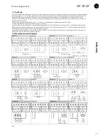
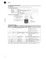
The diagrams below provide an overview of the functions of each terminal macro function, and a simplified connection diagram for each. 

7.2.


Macro Functions Guide Key 

STOP / RUN 


Latched input, Close to Run, Open to Stop 

Forward Rotation /Reverse Rotation  Selects the direction of motor operation 

AI1 REF   


Analog Input 1 is the selected speed reference 

P-xx REF   


Speed setpoint from the selected preset speed 

PR-REF 

Preset speeds H-20 – H-23 are used for the speed reference, selected according to other digital input 

status 

˄-FAST STOP (H-24)-˄ 


When both inputs are active simultaneously, the drive stops using Fast Stop Ramp Time H-24 

E-TRIP 

External Trip input, which must be Normally Closed. When the input opens, the drive trips showing 

E-trip

 or 

ptc-th

 depending on H-47 setting 

(NO) 


Normally Open Contact, Momentarily Close to Start 

(NC) 


Normally Closed Contact, momentary Open to Stop 

Fire Mode 


Activates Fire Mode, see section 7.7 Fire Mode 

ENABLE 

Hardware Enable Input. In Keypad Mode, H-31 determines whether the drive immediately starts, or the 

keypad start key must be pressed. In other modes, this input must be present before the start signal via 

the fieldbus interface 

INC SPD   


Normally Open, Close the input to Increase the motor speed 

DEC SPD   


Normally Open, Close input to Decrease motor speed 

KPD REF   


Keypad Speed Reference selected 

FB REF   


Selected speed reference from Fieldbus (Modbus RTU / CAN Open / Master depending on F-12 setting) 


7.3.


Macro Functions – Terminal Mode (F-12 = 0) 

H-15 

DI1 

DI2 

DI3 / AI2 

DI4 / AI1 

Diagram 


STOP 

RUN 

FWD 

P


REV 

Q


AI1 REF 

H-20 REF 

Analog Input AI1 

STOP 

RUN 

AI1 REF 

PR-REF 

H-20 

P-21 

Analog Input AI1 

STOP 

RUN 

DI2 

DI3 

PR 

H-20 - H-23 

F-01 

H-20 

P-21 

P-22 

H-23 

STOP 

RUN 

AI1 

H-20 REF 

E-TRIP 

OK 

Analog Input AI1 

STOP 

RUN 

AI1 

AI2 

Analog Input AI2 

Analog Input AI1 

STOP 

RUN FWD 

P


STOP 

RUN REV 

Q


AI1 

H-20 REF 

Analog Input AI1 

˄-----------FAST STOP (H-24)------------˄ 

STOP 

RUN 

FWD 

P


REV 

Q


E-TRIP 

OK 

Analog Input AI1 


STOP 

RUN FWD 

P


STOP 

RUN REV 

Q


E-TRIP 

OK 

Analog Input AI1 

˄-----------FAST STOP (H-24)---------------˄ 

STOP 

RUN 

FWD 

P


REV 

DI3 

DI4 

PR 

H-20 

P-21 

P-22 

H-23 

STOP 

START FWD 

P


STOP 

START REV 

Q


DI3 

DI4 

PR 

             ˄---------------FAST STOP (H-24)------------------˄ 

H-20 

P-21 

P-22 

H-23 

10 

(NO) 

START 

=


STOP 

(NC) 

AI1 REF 

H-20 REF 

Analog Input AI1 

11 

(NO) 

START FWD 

P


STOP 

(NC) 

(NO) 

START REV 

Q


Analog Input AI1 

               ˄-----------------------------FAST STOP (H-24)---------------------------------------------˄ 

12 

STOP 


RUN 

FAST STOP (H-24) 

OK 

AI1 REF 

H-20 REF 

Analog Input AI1 

13 

(NO) 

START FWD 

P


STOP 

(NC) 

(NO) 

START REV 

Q


KPD REF 

H-20 REF 

13 

 ˄-------------------------FAST STOP (H-24)----------------------------------------˄ 

14 

STOP 

RUN 

DI2 

E-TRIP 

OK 

DI2 

DI4 

PR 

11 

Summary of Contents for AF-70 LP

Page 1: ...ex geindustrial com GE Energy Connections AF 70 LP User Guide IP20 IP66 NEMA 4X AC Variable Speed Drive 0 37 22kW 0 5 30HP 200 480V ...

Page 2: ......

Page 3: ...tor Thermal overload Protection 15 4 10 EMC Compliant Installation 15 4 11 Optional Brake Resistor 15 5 Operation 16 5 1 Managing the Keypad 16 5 2 Operating Displays 16 5 3 Changing Parameters 16 5 4 Read Only Parameter Access 16 5 5 Resetting Parameters 16 5 6 Resetting a Fault 16 6 Parameters 17 6 1 Standard Parameters Group F 17 6 2 Extended Parameters Group H 18 6 3 Read Only Status Parameter...

Page 4: ...terms and conditions at their discretion and in all cases concerning warranty the local distributor should be contacted first This user guide is the original instructions document All non English versions are translations of the original instructions The contents of this User Guide are believed to be correct at the time of printing In the interest of a commitment to a policy of continuous improvem...

Page 5: ...imited by the fuses or MCB Suitably rated fuses or MCB should be fitted in the mains supply to the drive according to any local legislation or codes Do not carry out any work on the drive control cables whilst power is applied to the drive or to the external control circuits Within the European Union all machinery in which this product is used must comply with Directive 2006 42 EC Safety of Machin...

Page 6: ...EMC Filter Disconnect 27 7 Check the supply cable and motor cable for faults or short circuits 8 Route the cables 9 Check that the intended motor is suitable for use noting any precautions recommended by the supplier or manufacturer 4 10 EMC Compliant Installation 14 10 Check the motor terminal box for correct Star or Delta configuration where applicable 4 5 Motor Terminal Box Connections 12 11 En...

Page 7: ...potentiometer 5k 10kΩ between terminals 5 6 and 7 as shown o Adjust the potentiometer to vary the speed from F 02 0Hz default to F 01 50 60 Hz default Quick Start IP66 Switched Switch the mains power on to the unit using the built in isolator switch on the front panel The OFF REV FWD will enable the output and control the direction of rotation of the motor The potentiometer will control the motor ...

Page 8: ...of AF 70 Product numbering system diagram Product number for illustrative purposes only 7K LP 2 3 XXXX 9 X X A1 GE Product code 7K AF 7 Product series Drive Type LP AF 70 Micro Drive Input Voltage 2 230V 50 60Hz 4 400V 50 60Hz Input Phase 1 1 phase 3 3 phase Revision A1 1st revision B1 Future Dynamic Braking Module X No dynamic braking module no capability for braking AF 70 Size 1 only B Dynamic B...

Page 9: ...table for use in pollution degree 1 environments according to IEC 60664 1 For pollution degree 2 or higher environments drives should be mounted in a suitable control cabinet with sufficient ingress protection to maintain a pollution degree 1 environment around the drive Enclosures should be made from a thermally conductive material Ensure the minimum air gap clearances around the drive as shown b...

Page 10: ...tically on a suitable flat surface The minimum mounting clearances as shown in the table below must be observed The mounting site and chosen mountings should be sufficient to support the weight of the drives Using the drive as a template or the dimensions shown above mark the locations required for drilling Suitable cable glands to maintain the ingress protection of the drive are required Gland ho...

Page 11: ...For conduit installations the conduit entry holes require standard opening to the required sizes specified per the NEC Not intended for installation using rigid conduit system Power Isolator Lock Off On the switched models the main power isolator switch can be locked in the Off position using a 20mm standard shackle padlock not supplied IP66 Nema 4X Gland Plate IP66 Nema 4X Unit Lock Off 3 8 Remov...

Page 12: ...impedance must conform to the requirements of national and local industrial safety regulations and or electrical codes The integrity of all ground connections should be checked periodically Protective Earth Conductor The Cross sectional area of the PE Conductor must be at least equal to that of the incoming supply conductor Safety Ground This is the safety ground for the drive that is required by ...

Page 13: ...itions occur o The incoming supply impedance is low or the fault level short circuit current is high o The supply is prone to dips or brown outs o An imbalance exists on the supply 3 phase drives o The power supply to the drive is via a busbar and brush gear system typically overhead Cranes In all other installations an input choke is recommended to ensure protection of the drive against power sup...

Page 14: ...d controlled from the Local POT Run in Auto 0 Speed controlled using Analog input 2 e g from PLC with 4 20mA signal Run in Speed Control STOP Run in PI Control 5 1 In Speed Control the speed is controlled from the Local POT In PI Control Local POT controls PI set point Run in Preset Speed Control STOP Run in PI Control 5 0 2 4 5 8 12 In Preset Speed Control H 20 sets the Preset Speed In PI Control...

Page 15: ...y Cable Type Motor Cable Type Control Cables Maximum Permissible Motor Cable Length C1 6 Shielded 1 Shielded 1 5 Shielded 4 1M 5M 7 C2 Shielded 2 Shielded 1 5 5M 25M 7 C3 Unshielded 3 Shielded 2 25M 100M 7 1 A screened shielded cable suitable for fixed installation with the relevant mains voltage in use Braided or twisted type screened cable where the screen covers at least 85 of the cable surface...

Page 16: ...ameter values to their factory default settings press and hold Up Down and Stop buttons for 2 seconds The display will show p def H 50 0 Drive is enabled running display shows the output frequency Hz F 01 Use the up and down keys to select the required parameter F 00 Use the up and down keys to select P 00 A 2 3 Press the Navigate key for 1 second The display will show the motor current Amps F 08 ...

Page 17: ...otor nameplate enables the slip compensation function and the AF 70 display will now show motor speed in RPM All speed related parameters such as Minimum and Maximum Speed Preset Speeds etc will also be displayed in RPM Note If F 09 value is changed F 10 value is reset to 0 F 11 Low Frequency Torque Boost Current 0 0 Drive Dependent Drive Dependent Low frequency torque can be improved by increasin...

Page 18: ... maximum effective switching frequency of the drive If rEd is displayed when the parameter is viewed the switching frequency has been reduced to the level in DR 32 due to excessive drive heatsink temperature H 18 Output Relay Function Select 0 9 1 Selects the function assigned to the relay output The relay has two output terminals Logic 1 indicates the relay is active and therefore terminals 10 an...

Page 19: ...al Input 1 is closed Auto 1 To Auto 5 Following a trip the drive will make up to 5 attempts to restart at 20 second intervals The numbers of restart attempts are counted and if the drive fails to start on the final attempt the drive will trip with a fault and will require the user to manually reset the fault The drive must be powered down to reset the counter Index 2 Fire Mode Input Logic 0 1 0 De...

Page 20: ...ot trip H 37 Access Code Definition 0 9999 101 Defines the access code which must be entered in F 14 to access parameters above F 14 H 38 Parameter Access Lock 0 1 0 0 Unlocked All parameters can be accessed and changed 1 Locked Parameter values can be displayed but cannot be changed except H 38 H 39 Analog Input 1 Offset 500 0 500 0 0 0 Sets an offset as a percentage of the full scale range of th...

Page 21: ...l 3 BLDC motor vector speed control 4 Synchronous Reluctance motor vector speed control 5 LSPM motor vector speed control H 52 Motor Parameter Autotune 0 1 0 0 Disabled 1 Enabled When enabled the drive immediately measures required data from the motor for optimal operation Ensure all motor related parameters are correctly set first before enabling this parameter This parameter can be used to optim...

Page 22: ...me with heatsink 85ᵒC Hours Total accumulated hours and minutes of operation above heatsink temp of 85ᵒC DR 24 Accumulated time with drive internal temp 80ᵒC Hours Total accumulated hours and minutes of operation with drive internal ambient above 80 C DR 25 Estimated rotor speed Hz In vector control modes estimated rotor speed in Hz DR 26 kWh meter MWh meter Total number of kWh MWh consumed by the...

Page 23: ...t Stop Ramp Time H 24 E TRIP External Trip input which must be Normally Closed When the input opens the drive trips showing E trip or ptc th depending on H 47 setting NO Normally Open Contact Momentarily Close to Start NC Normally Closed Contact momentary Open to Stop Fire Mode Activates Fire Mode see section 7 7 Fire Mode ENABLE Hardware Enable Input In Keypad Mode H 31 determines whether the dri...

Page 24: ... DI4 AI1 Diagram 0 1 0 1 0 1 0 1 0 STOP ENABLE FB REF Fieldbus Speed Reference Modbus RTU CAN Master Slave defined by F 12 14 1 STOP ENABLE PI Speed Reference 15 3 STOP ENABLE FB REF H 20 REF E TRIP OK Analog Input AI1 3 5 STOP ENABLE FB REF PR REF H 20 P 21 Analog Input AI1 1 START F 12 3 or 4 Only 6 STOP ENABLE FB REF AI1 REF E TRIP OK Analog Input AI1 3 START F 12 3 or 4 Only 7 STOP ENABLE FB R...

Page 25: ...ure Th FLt Faulty Thermistor on Heat sink E trip External Trip 4 20 F 4 20mA fault Ph Ib Phase Imbalance P Loss Input Phase Loss Trip SC trp Communications Loss Trip I t trp Accumulated overload Trip The following faults will result in a drive trip auto reset and restart O Volt Over Voltage on DC Bus U Volt Under Voltage on DC Bus h O I Fast Over current Trip O I Instantaneous over current on driv...

Page 26: ...F 04 High Decel Ramp 2 H 24 Bit 2 Low No Function High Fault Reset Bit 3 Low No Function High Coast Stop Request 2 R W Modbus Speed reference setpoint 0 5000 Setpoint frequency x10 e g 100 10 0Hz 4 R W Acceleration and Deceleration Time 0 60000 Ramp time in seconds x 100 e g 250 2 5 seconds 6 R Error code Drive status Low Byte Drive Error Code see section 10 1 High Byte Drive Status as follows 0 D...

Page 27: ... V 3 Phase Input 3 Phase Output 1 0 37 0 5 3 4 6 6 8 8 2 3 1 0 75 1 5 6 10 10 8 8 4 3 1 1 5 2 9 5 16 15 8 8 7 2 1 5 2 8 9 16 15 8 8 7 100 2 2 2 3 12 1 16 17 5 8 8 10 5 50 3 4 5 20 9 32 30 8 8 18 25 3 5 5 7 5 26 4 40 35 8 8 24 20 4 7 5 10 33 3 40 45 16 5 30 15 4 11 15 50 1 63 70 16 5 46 10 380 480 10 V 3 Phase Input 3 Phase Output 1 0 75 1 3 5 6 6 8 8 2 2 1 1 5 2 5 6 10 10 8 8 4 1 2 1 5 2 5 6 10 10...

Page 28: ...shown in section 9 2 and the National Electrical Code or other applicable local codes Motor Cable 75 C Copper must be used Power cable connections and tightening torques are shown in sections 3 3 and 3 5 Integral Solid Sate short circuit protection does not provide branch circuit protection Branch circuit protection must be provided in accordance with the national electrical code and any additiona...

Page 29: ...ory Default parameters loaded E trip 11 External trip E trip requested on digital input 3 Normally closed contact has opened for some reason If motor thermistor is connected check if the motor is too hot SC ObS 12 Optibus comms loss Check communication link between drive and external devices Make sure each drive in the network has its unique address FLt dc 13 DC bus ripple too high Check incoming ...

Page 30: ...AF 7 AF 70 LP Intro 30 Notes ...

Page 31: ......

Page 32: ...9 0 2233 9719 0 Hungary GE Hungary Kft Vaci ut 81 83 H 1139 Budapest Tel 36 1 447 6050 Italy GE Industrial Solutions Centro Direzionale Colleoni Via Paracelso 16 Palazzo Andromeda B1 I 20864 Agrate Brianza MB Tel 39 039 637 371 Netherlands GE Industrial Solutions Parallelweg 10 NL 7482 CA Haaksbergen Tel 31 0 53 573 03 03 Poland GE Power Controls Ul Towarowa 25A Ip 00 869 Warszawa Tel 48 22 520 53...

Reviews: