7 Protection Parameter Settings
P50 Agile P153
7-14
P153/EN M/B
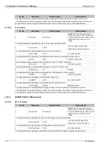
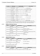
Sr. No
Parameter
Default setting
Setting Range
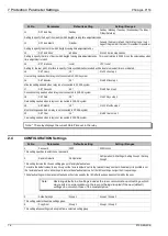
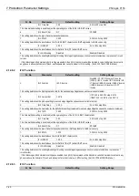
1.
IN1>3 Function
IEC S Inverse
Disabled / DT / IEC S Inverse / S Inverse
(1.3Sec) / IEC V Inverse / IEC E Inverse / UK
LT Inverse / IEEE M Inverse / IEEE V Inverse
/ IEEE E Inverse / US Inverse / US ST
Inverse
This setting determines the tripping characteristic for the third stage measured earth fault element.
2.
IN1>3 Current Set
01.00*In
If DT 1.0 to 35.00*In step 0.01*In
If IDMT 0.05 to 4.00*In step 0.01*In
This setting determines the pick-up setting for third stage measured earth fault element.
3.
IN1>3 Time Delay
1.00 S
0s to 200s step 0.01s
This setting determines the time-delay for the definite time setting if selected for third stage of measured earth fault element.
4.
IN1>3 TMS
1.000
0.025 to 1.2 step 0.005
This time multiplier setting is used to adjust the operating time of the IEC / UK IDMT characteristic.
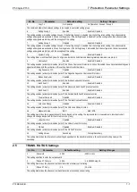
5.
IN1>3 Time Dial
1.00
0.01 to 100 step 0.01
This time multiplier setting is used to adjust the operating time of the IEEE / US IDMT curves.
6.
IN1>3 Reset Char
DT
DT/IDMT
This setting determines the type of reset/release characteristics. IDMT applicable for IEEE curves only.
7.
IN1>3 RTMS
1.000
0.025 to 1.2 step 0.005
This setting determines the reset/release time for IEEE IDMT characteristic
8.
IN1>3 tRESET
1.00 S
0s to 100s step 0.01s
This setting determines the reset/release time for Definite Time (DT) and all IDMT curve
9.
IN1>3 2H Blocking
Disabled
Enabled / Disabled
This setting determines the enabling/disabling of blocking third stage measured earth fault element due to presence of inrush current.
If IN1>3 Blocking and 2nd Harmonic settings are enabled, then (IN1>3) trip command will be blocked in case 2nd harmonics content in
any phase is above the 2ndHarm Thresh. and fundamental current is below I> lift 2H setting . (Set in SYSTEM CONFIG Menu.)
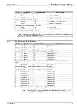
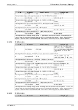
2.12.4
EARTH FAULT 2 (Derived)
2.12.4.1
IN2>1 Function
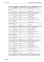
Sr. No
Parameter
Default setting
Setting Range
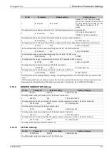
1.
IN2>1 Function
IEC S Inverse
Disabled / DT / IEC S Inverse / S Inverse
(1.3Sec) / IEC V Inverse / IEC E Inverse / UK
LT Inverse / IEEE M Inverse / IEEE V Inverse
/ IEEE E Inverse / US Inverse / US ST
Inverse
This setting determines the tripping characteristic for the first stage derived earth fault element.
2.
IN2>1 Current Set
1.00*In
If DT 0.10 to 35.00*In step 0.01*In
If IDMT 0.10 to 4.00*In step 0.01*In
This setting determines the pick-up setting for first stage derived earth fault element.
3.
IN2>1 Time Delay
1.00 S
0s to 200s step 0.01s
This setting determines the time-delay for the definite time setting if selected for first stage of derived earth fault element.
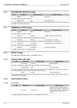
4.
IN2>1 TMS
1.000
0.025 to 1.2 step 0.005
This time multiplier setting is used to adjust the operating time of the IEC / UK IDMT characteristic.
5.
IN2>1 Time Dial
1.00
0.01 to 100 step 0.01
This time multiplier setting is used to adjust the operating time of the IEEE / US IDMT curves.
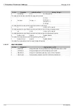
6.
IN2>1 Reset Char
DT
DT/IDMT
This setting determines the type of reset/release characteristics. IDMT applicable for IEEE curves only.
Summary of Contents for Agile P50 Series
Page 3: ...P50 Agile P153 1 Introduction P153 EN M B 1 1 INTRODUCTION CHAPTER 1...
Page 4: ...1 Introduction P50 Agile P153 1 2 P153 EN M B...
Page 10: ...1 Introduction P50 Agile P153 1 8 P153 EN M B...
Page 11: ...P50 Agile P153 2 Safety Information P153 EN M A 2 1 SAFETY INFORMATION CHAPTER 2...
Page 22: ...Chapter 2 Safety Information P50 Agile P153 2 12 P153 EN M A...
Page 23: ...P50 Agile P153 3 Hardware Design P153 EN M B 3 1 HARDWARE DESIGN CHAPTER 3...
Page 24: ...3 Hardware Design P50 Agile P153 3 2 P153 EN M B...
Page 32: ...3 Hardware Design P50 Agile P153 3 10 P153 EN M B...
Page 33: ...P50 Agile P153 4 Front Panel P153 EN M B 4 1 FRONT PANEL CHAPTER 4...
Page 34: ...4 Front Panel P50 Agile P153 4 2 P153 EN M B...
Page 39: ...P50 Agile P153 5 Configuration P153 EN M B 5 1 CONFIGURATION CHAPTER 5...
Page 40: ...P50 Agile P153 5 Configuration P153 EN M B 5 2...
Page 150: ...P50 Agile P153 5 Configuration P153 EN M B 5 112...
Page 151: ...P50 Agile P153 6 Protection Functions P153 EN M B 6 1 PROTECTION FUNCTIONS CHAPTER 6...
Page 152: ...6 Protection Functions P50 Agile P153 6 2 P153 EN M B...
Page 168: ...7 Protection Parameter Settings P50 Agile P153 7 2 P153 EN M B...
Page 189: ...P50 Agile P153 8 Monitoring Control P153 EN M B 8 1 MONITORING CONTROL CHAPTER 8...
Page 190: ...8 Monitoring Control P50 Agile P153 8 2 P153 EN M B...
Page 207: ...P50 Agile P153 9 SCADA Communications P153 EN M B 9 1 SCADA COMMUNICATIONS CHAPTER 9...
Page 208: ...12 SCADA Communications P50 Agile P153 9 2 P153 EN M B...
Page 220: ...12 SCADA Communications P50 Agile P153 9 14 P153 EN M B...
Page 221: ...P50 Agile P153 10 Installation P153 EN M B 10 1 INSTALLATION CHAPTER 10...
Page 222: ...10 Installation P50 Agile P153 10 2 P153 EN M B...
Page 234: ...13 Commissioning Instructions P50 Agile P153 13 2 P153 EN M B...
Page 242: ...12 Maintenance and Troubleshooting P50 Agile P153 12 2 P153 EN M B...
Page 250: ...12 Maintenance and Troubleshooting P50 Agile P153 12 10 P153 EN M B...
Page 252: ...13 Technical Specifications P50 Agile P153 13 2 P153 EN M B...
Page 263: ...P50 Agile P153 14 Wiring Diagrams P153 EN M B 14 1 WIRING DIAGRAMS CHAPTER 14...
Page 264: ...14 Wiring Diagrams P50 Agile P153 14 2 P153 EN M B...
Page 267: ......


