
Power Circuit Bre akers Types AK-2-15 and AK-2/3-25 GEI-50299
ment pin
(15)
on the center pole into position.
Be sure the stationary insulation barriers
are correctly located.
4.
A lign the cross bar with the left and right
pole pivot supports and install the left and
right pole movable contacts. Use the bullet
nosed steel pin to aid in aligning the holes
in the cross bar, the contacts and the pivot
supports.
5.
Install the left and right pole pivot pins while
threading them through the spring c lips and lock
the spring c lips
(9).
Be sure the pivot pins
are fully inserted.
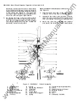
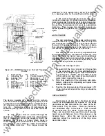
6. Adjust the contact wipe to
1/8"
.:!:.
1/32"
by
adjusting the eccentric contact wipe adjusting
pin
(15).
The breaker must be open to adjust
the wipe. In the event acceptable wipe cannot
be obtained by moving the contact wipe ad
justing pin
(15),
from the movable contact
forward or backward as necessary to bring
the wipe within the range of the contact wipe
adjusting pin
(15).
Do not exceed the recom
mended settings for wipe;
otherwise the
breaker may not c lose comp lete ly .
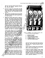
When
viewed from the top with the breaker c losed,
the m�vable contact should be centrally located
with respect to the stationary contacts.
If
the movable contacts are not centrally located
as shown in section CC, form the movable
contacts until they are nominally �entered.
If
the moving contacts are not centered with
1/8"
separation when closed against the fixed
contacts, they shou ld be bent laterally (after
opening the breaker contacts) .
To do this
without squeezing the two movable contact
arms together, a
1/8"
spacer p late should be
inserted between them; then the pair c an be
grasped with p liers and bent in the desired
direction for centering.
New contacts should be adjustable using
eccentric numbers
1, 2,
or
3.
These numbers
are the ones visible when viewing the breaker
from the front, not from above . (The higher
numbers should be reserved for tightening
at future maintenance readjustments after
wear.)
Also,
if
higher numbers are used,
where adequate wipe is obtainable at settings
1, 2,
or
3,
it is possible that the stationary
contacts will bottom, producing excessive back
force on the breaker c losing mechanism so that
the toggle link will not pass center. As a
result, the breaker wi ll not complete its stroke,
and inadequate pressure and wipe will result;
burn-up of contacts from just load current
will follow.
If
the required wipe of new contacts c annot be
obtained with eccentric number of
3
or lower,
bending of the contact arms toward the closed
position is required.
This should be done
individually, using an
8"
C rescent or
1/2 - 5/8"
tapered open end wrench to grasp the contact
and a
10"
C rescent or the
1" - 1-1/8"
tapered
1
2
3
4
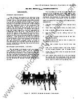
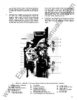
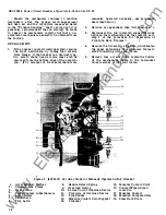
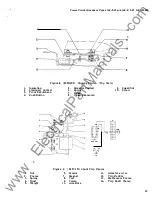
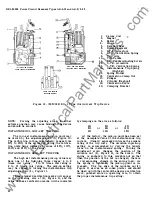
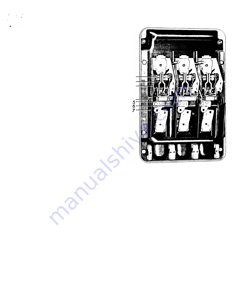
Figure 4 .
(8039851) AK-2-25
Back F rame - Loca
tion of C rossbar and Po le Shields
1.
Stationary Contacts
2.
Movab le Contacts
3.
Upper Stud Asbestos Shield
4 . Crossbar Plastic End Shield
5.
Crossbar Assem'bly
6 . C rossbar As bestos Inner Shield
7 .
Lower Stud Asbestos Shie ld
open-end wrench to grasp the pivot portion of
the arm. The soft copper arm will bend with
little difficulty.
Both arms shou ld be bent
identically.
Operate breaker several times, and recheck
wipe to make sure bending of movable arms
did not occur in these operations.
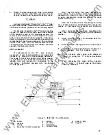
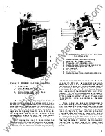
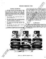
7.
Operate the bre aker manually several times
to assure proper functioning occurs, then
rep lace the U shaped insulation
(5)
Figure
3
and arc quenchers. When rep lacing the arc
quenchers be sure the quencher is seated
downward completely and that the quencher
clamp covers the knobs protruding through
the arc quencher insulation.
11
www
. ElectricalPartManuals
. com


