
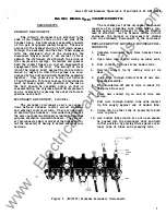
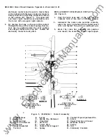
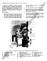
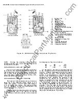
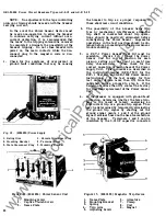

CONTACT SPRINGS
( 1 9)
Figure
3
A minimum force of 5 lbs and a maximum
force of
9
lbs. should be required to begin move
ment of a single stationary contact from the open
position towards the closed position. This may
be checked by using a push scale applied at the
point at which the movable contact touches the
stationary contact.
If
these pressures are not
obtained or if the spring is damaged, replacement
is required.
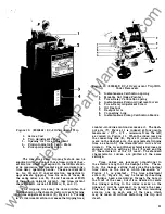
In order to replace the contact spring the upper
stud
(17)
must be removed. The hardware which
fastens the stud to the breaker base consists of
two screws
( 1 6),
and nut
(20).
When These are
removed, the stud may be withdrawn from the
base in a forward direction. After the stud has
been removed, it is a simple matter to disconnect
the two ends of the spring
(1 9)
and replace it
with a new one.
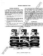
MECHANISM
The breaker mechanism is a spring actuated,
over-center toggle type of mechanism. As the
closing force is applied, either by movement of the
operating handle or the closing solenoid armature,
energy is stored in the operating springs. After
the springs have gone over center, movement of the
output crank of the mechanism is still blocked
for a time by a cam arrangement. As the springs
are further extended, the blocking cam moves
away from the output crank, and the springs are
allowed to discharge part of their stored energy,
closing the breaker contacts.
This assures a fast-snapping closing action
regardless of the speed at which the closing handle
is operated.
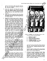
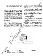
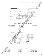
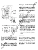
The breaker mechanism is tripped by the
displacement of the trip latch
(7),
Figure
6.
Looking at the breaker from the right hand side
as in Figure
5,
the tripping movement of the latch
is counter-clockwise.
Operation of any of the
automatic trip devices or the trip push button
causes the latch to move in the tripping direction.
When the latch moves off tbe trip latch roller
(7),
the remaining force in the operating spring causes
the mechanism toggle to collapse, resulting in the
opening of the breaker contacts.
ADJUSTMENT
Since all the mechanism adjustments are
carefully set by experienced factory personnel
after assembly at the factory, it should normally
not be necessary to make any adjustments in the
field. At the time of installation, and also in the
course of a maintenance inspection,
if
the breaker
functions properly through several repeated opera
tions, it is best to assume that adjustments are
satisfactory.
If
the breaker mechanism does not function
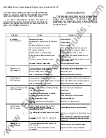
properly, it is best to first perform the available
remedial measures listed in the "Trouble Shooting"
chart of these instructions. One of the remedies
1 2
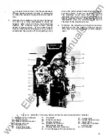
listed i s that of proper mechanism latch engage
ment, the amount of engagement be.tween the latch
(7)
and latch roller (5), Figure
6.
This is the only
adjustment that is required on the breaker mech
anism, and proper latch engagement is obtained in
the following manner:
(NOTE - Before making latch adjustments, check
to make sure that the buffer paddle which stops
against the end of the latch adjustment screw is
rigidly fastened to the trip shaft. Hold the trip
shaft (8), Figure 5, steady and attempt to move
the buffer paddle.
If
any relative movement
between the two is noted, tighten the fasteners
holding the buffer paddle to the trip shaft.)
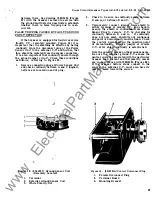
Latch Adjustment - Manual Breaker
1 .
Locate the latch adjustment screw on the
lower, outer side of the right-hand mechanism
side frame. This screw is threaded through
a nylon insert locknut which, in turn, is welded
to a projecting bracket on the side frame.
·
2 .
Rotate the closing handle 90 degrees counter
clockwise, setting the closing mechanism in
the reset position. Turn the adjusting screw
into the locknut until the closing mechanism
trips open, the closing handle returning to its
normal vertical position.
NOTE:
KEEP
HANDS CLEAR OF THE CLOSING HANDLE
WHEN MAKING THIS ADJUSTMENT.
3. Withdraw the adjusting screw from the locknut
1/4
turn at a time, attempting to close the
breaker after eaeh
1/4
turn, and observing
whether the contacts move toward closing
before tripping occurs.
If
the contacts move
before tripping occurs, you have established
the position of the adjusting screw where the
latch and latch roller begin to engage. In
some cases, it may be necessary to turn the
adjusting screw less than
1/4
turn in order
to establish the position where the contacts
begin to move before tripping occurs. When
this position is established, note the position
of the slot in the head of the adjusting screw.
4 .
Withdraw the adjusting screw three and one
half turns from the position noted in step 3.
This sets the proper amount of latch engage
ment.
Latch Adjustment - Electrical Breaker
1 .
Locate the latch adjustment screw on the
lower, outer side of the right mechanism
side frame. This screw is threaded through
a nylon insert locknut which, in turn, is
welded to a projecting bracket on the side
frame.
2.
With the breaker in the open position turn the
adjusting screw into the locknut one complete
turn at a time, closing the breaker after each
complete turn of the adjusting screw, until
•
www
. ElectricalPartManuals
. com


