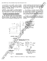

GEI-50299 Power Circuit Breakers Types
AK-2 -15
and
AK-2/3 -2 5
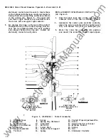
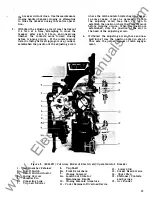
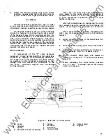
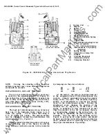
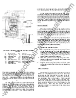
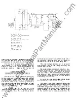
CUT-OFF SWITCH
Figure
7.
As
under "Operation", the function
of the
switch is to de-energize the
"X"
contactor coil and energize the
"Y"
relay coil
as the breaker mechanism moves from the opened
to
the closed position.
The switch is operated by the movement of
a mechanism link against the switch actuator
(6).
This causes the actuator and movable contact
assembly (4) to rotate counterclockwise about
pin
(7),
opening the "bb" contacts
(8)
and closing
the "aa" contacts at
(9).
Overtravel of the
actuator
(6)
beyond the point of making contact
at
(9)
is absorbed by spring
(5)
which couples
the movable contact (4) to the actuator. Spring
(3)
resets the switch after the breaker contacts
open and the breaker mechanism resets.
The point at which the cutoff switch operates
during the breaker closing cycle is after the spring
charged mechanism has been driven over-center.
This assures that the cutoff switch cannot operate
too early in the breaker closing cycle, thus the
X
and
Y
relays are de-energized and energized,
respectively, at the proper time and the circuits
anti-pump feature is maintained. When the closing
mechanism is driven over-center, the force of
the previously charged closing springs is released,
closing the breaker.
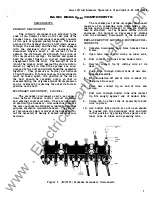
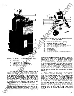
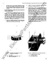
REPLACEMENT
The cut-off switch is located above the breaker
mechanism.
It
is fitted between the upper portions
of the steel side plates that make up the mechanism
frame. A raised horizontal ridge on each side of
the molded body of the switch fits into a cor
responding groove in each of the steel side plates.
A round head screw
on each side fastens the
switch and side plate together. Replacement of
the switch is accomplished by the following pro
cedure:
1 .
Remove the cover on the top of the switch
by taking out the two screws which hold it
in place.
2.
After taking careful note of the connection
arrangements, disconnect the leads from the
switch terminals.
3.
Remove the two screws, one on each side,
which fasten the switch to the mechanism
side plates.
Note that the one on the right
hand side also holds a wiring cleat and spacer
which serves to hold the wires clear of the
link connecting the mechanism and the breaker
position indicator.
4.
Remove the front escutcheon from the breaker.
5.
Slide the cut-off switch out from between the
steel side plates by pulling straight forward.
18
6.
Mount the replacement switch by reversing
the order
of
procedure.
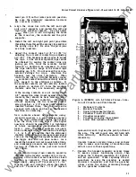
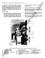
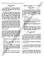
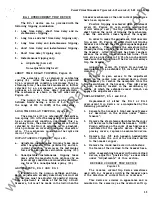
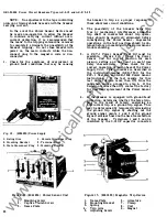
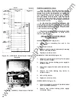
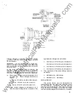
CLOSING SWITCH
Figure
8.
The closing switch is mounted on the upper
flange of the closing solenoid coil. A hole in the
escutcheon
(3)
permits access to the switch button
When the button i s pressed, movable contact
deflects and impinges upon stationary contact
(2) .
This energizes the
"X"
relay coil which
seals itself in, and, in turn, energizes the closing
solenoid.
REPLACEMENT
1.
Remove escutcheon
(3
).
2.
Disconnect leads from switch terminals.
3.
Deflect the left end of hinge
(7)
to the left
so that the movable contact
(5)
may be dis
engaged from the switch assembly.
4. Removal of the two screws
(10)
from speed
nuts
(9)
completes the disassembly of the
switch.
5.
Reassembly with new parts is a matter of
reversing the described procedure.
In
re
assembling, be sure the tab on the left end
of
hinge
(7)
is bent to the right far enough to
avoid any possibility that movable contact
(5)
might become free of the assembly.
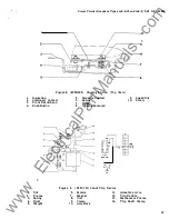
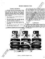
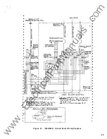
SHUNT TRIP DEVICE
Figure
9.
The shunt trip device is mounted underneath
the horizontal cross frame member,
just to the
left of the front escutcheon.
It is composed
of a magnet, coil and armature. The armature
has an extended arm or striker
(11)
which bears
against the
paddle
( 12 )
on the trip shaft
when the coil
is energized. This displaces
the trip latch in the breaker mechanism, opening
the breaker contacts.
The trip device is generally activated by a
remote switch or relay which closes the shunt
trip coil circuit.
In
order to avoid unnecessary heating of the
coil of the device, an auxiliary switch "a" contact
is wired in series with the coil . This prevents
the energization of the coil
if
the breaker is open.
REPLACEMENT
The entire shunt trip device may be dis
mounted by disconnecting the coil leads and re
moving nuts
(1).
However, the only part of the
device that might conceivably need replacement
during the life of the breaker is the coil
(8).
This
•
www
. ElectricalPartManuals
. com


