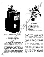


Power Circuit Breakers
Types AK-2 -15
and
AK-2/3-25 GEI-50299
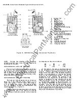
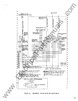
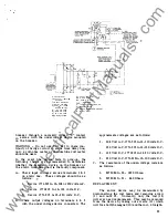
EC- 1 OVERCURRENT TRIP DEVICE
The
EC-1
device can be provided with the
following tripping combination
1 . Long time delay, short time delay and in-
stantaneous -tripping.
2 . Long time and short time delay tripping only.
3 . Long time delay and instantaneous tripping.
4. Short time delay and instantaneous tripping.
5 .
Short time delay tripping only.
6. Instantaneous tripping only.
a. Adjustable (Low set)
or
Non-adjustable (High set)
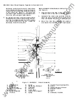
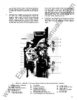
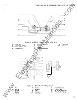
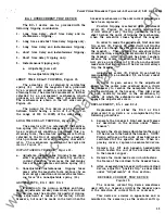
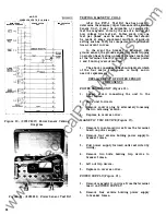
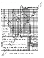
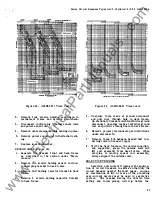
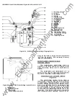
SHORT TIME DELAY TRIPPING, Figure 12.
The armature
(7)
is retained by calibrating
spring (8).
Mter the magnetic force, produced
by an overcurrent condition, overcomes this re
straining force, the armature movement is further
retarded by an escapement mechanism which
produces an inverse time delay characteristic.
The mechanism is shown in the left Side view of
Figure -12.
The pickup for this device can be field set
between limits having a ratio of 2- 1/2 to 1 in
the range of 200 to 1000% of the coil rating.
LONG TIME DELAY TRIPPING, Figure 12
The armature (12), is retained by the calibra
tion spring (13). After the magnetic force, produced
bs an overcurrent condition, overcomes this re
straining force, the armature movement is further
retarded by the flow of silicone oil in a dashpot,
which produces an inverse time delay character
istic. The mechanism is shown in the right side
view of Figure 12.
INSTANTANEOUS TRIPPING, Figure 1 2 .
a. Adjustable instantaneous tripping takes place
after the magnetic force produced by an over
current condition, overcomes the restraining
force of the adjustable calibration spring (13).
b. Nonadjustable instantaneous tripping takes
place after the magnetic force produced by an
overcurrent condition overcomes the restrain
ing force of a nonadjustable spring (14).
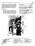
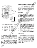
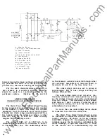
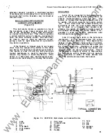
ADJUSTMENTS, EC- 1 AND EC-2
In addition to the pick-up settings and time
delay adjustments already described, overcurrent
trip devices must be adjusted for positive tripping.
This adjustment is made at the factory on new
breakers, but must be made in the field when the
breaker mechanism or the overcurrent trip devices
have been replaced.
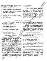
Positive tripping is achieved when adjustment
s crew (2), Figure 10, is in such a position that
it will always carry the trip paddle on the trip
shaft beyond the point of tripping the mechanism,
when the armature closes against the magnet.
In order to make the adjustment, first unscrew
trip screw (2 ), Figure 10, until it will not trip the
breaker even though the armature is pushed against
the magnet.
•
Then, holding the armature in the
closed position, advance the scl"ew until it just trips
the breaker. Mter this point has been reached,
advance the screw two additional full turns . This
will give an overtravel of 1/16 of an inch and will
make sure that activation of the device will always
trip the breaker.
Adjustment screw (2), Fi�re 10, can best be
manipulated by an extended 1/4 inch hex socket
wrench.
In
order to gain access to the adjustment
screw on the center pole overload device, it will
be necessary to remove the nameplate from the
front escutcheon of the breaker. This will reveal
a hole, centrally located in the escutcheon, by
means of which the extended socket wrench can
engage the adjustment screw.
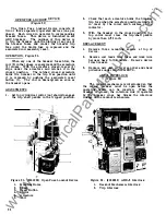
REPLACEMENT, EC- 1 and EC-2
Replacement of either the EC-1 or EC-2
overcurrent trip device is accomplished by the
following procedure:
1 . Separate the breaker 's front and back frames
as described in the section under "Main
tenance" .
2 . Remove the steel clamps which fasten the cover
of the device to the back of the breaker. NOTE :
Pickup settings on the cover of each device are
calibrated for the specific device. When re
placing covers, replace on associated device.
3.
Remove the 3/8 inch hexagon headed bolts
which fasten the coil of the overload device
to the breaker copper.
4 . Remove the round head screw which fastens
the frame of the overload to the breaker base.
5.
Mter reassembling breaker with new overload
device, adjust for "positive trip" as described
under "Adjustments" of this section.
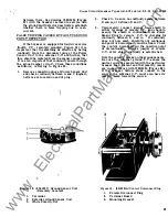
REVERSE CURRENT TRIP DEVICE
Figure 1 3 .
The reverse current trip device sometimes
used with d-e breakers will trip the breaker open
if
the direction of current flow is reversed.
This device is similar in appearance and is
mounted in the same way as the overcurrent trip.
23
www
. ElectricalPartManuals
. com


