

13
1,2
8 3
POLE BREAKER
WER�NT
'
- �'
R C
,
._/COIL
, _ _ _
1 _
osu
(Wt£N REQ'O)
070
coo
L3
AIO
oso
I�
.2_
52
R. C.
POITNTIAL
COL
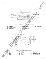
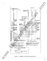
WIRING
TYPICAL
CONNECTION DIAGRAM
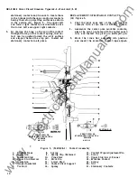
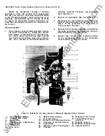
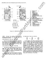
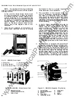
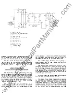
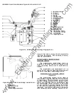
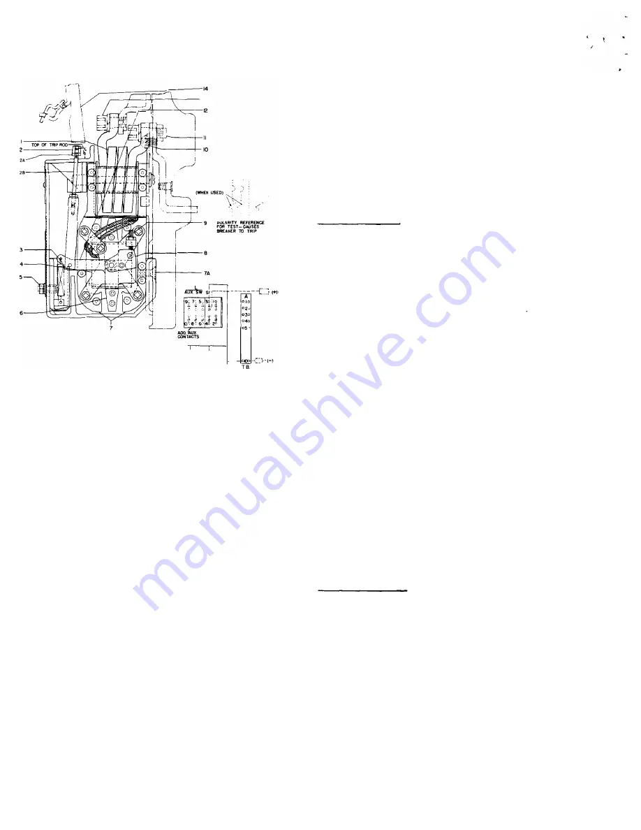
Figure 13. (2 8 6B209) Reverse Current Tripping
Device
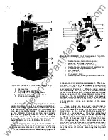
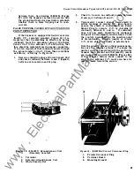
1 .
2 .
2A.
2B.
3.
4.
5 .
6 .
7 .
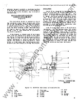
Series Coil
Adjusting Nut
Locking Nut
Trip Rod
Spring
Potential Coil
Calibration Nut
Armature
Pole Pieces
7A.
8 .
9 .
10. '
1 1 .
1 2 .
1 3 .
1 4 .
Screws
Counterweight
Stop Screw
Mounting Screw
Screw (Lower Stud)
Trip C rank
Screw (Lower Stud)
Trip Paddle
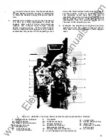
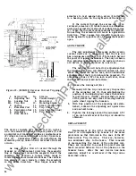
The device consists of a series coil (1), with an
iron core mounted between two pole pieces
(7)
and
a potential coil connected across a constant source
of voltage and mounted around a rotary type arma
ture (6).
Calibration spring (3) determines the
armature pick-up value when a reversal of current
occurs.
As long as the flow of current through the
breaker is in the normal direction, the magnetic
flux of the series coil and the magnetic flux of the
potential coil produce a torque which tends to
rotate the armature counterclockwise. The calibra
tion spring (3) also tends to rotate the armature
in the same direction.
This torque causes the
24
armature to rest against stop screw (9) attached
to a bearing plate on the right side of the device.
If
the current through the series coil (1) is
reversed, armature (6) tends to move in a clockwise
direction against the restraint of calibration spring
(3 ) . When the current reversal exceeds the calibra
tion setting, the armature will move in a clockwise
direction. This causes trip rod (2B) to move up
wards against trip paddle (14), tripping the breaker
open.
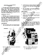
ADJUSTMENTS
The only adjustment to be made on the reverse
current device is to make sure that the trip rod
has a minimum overtravel of 1/32 of an inch beyond
the point of tripping the breaker. The only occasion
this adjustment should have to be made is when an
old device is being replaced by a new one .
The new device will be factory adjusted so that
the top end of the trip rod (2B ) will extend 1/2 inch
above the top of the device case, and no additional
adjustments of the trip rod should be required. To
obtain the proper 1 /32 of an inch overtravel, close
the breaker and proceed as follows :
1 . Loosen the locking nut (2A).
2 . Manually lift the trip rod and vary the position
of the adjusting nut (2), thus establishing the
position of the adjusting nut where the breaker
is just tripped. (NOTE - Be sure that all parts
of the person are kept clear of moving breaker
parts when tripping the breaker.
3 . With this position of the adjusting nut estab
lished, advance the adjusting nut upward one
and one half turns.
4 . Tighten the locking nut and the minimum 1/32
of an inch overtravel of the trip rod should be
obtained.
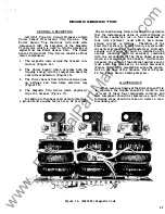
REPLACEMENT
Replacement of the ED- 1 Reverse Current
Device is accomplished by means of the same
procedure as that followed in the case of the E C
Overcurrent Trip Devices. There i s , however,
one additional step to the taken. This consists
of disconnecting the leads of the potential coil.
These are connected to a small two point terminal
board mounted between two of the phases on the
breaker base.
After the new device has been
installed, adjust for overtravel of the trip rod as
described above.
www
. ElectricalPartManuals
. com


