
..
r
r
'
P0\1\/ER CIRCUIT BREAKERS
Types
AK·2·1S
and
AK·2/3·25
I NTROOUCT ION
The instructions contained herein provide in
formation for
maintenance procedures
and for replacing
breaker compo
nents and accessories. For information regarding
the receiving, handling, storage and installation
of these breakers, refer to GEK-7302 furnished
with all AK breakers.
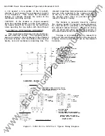
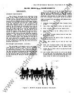
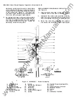
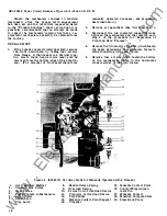
OPERATION
ELECTRICAL OPERATION
Figure 1
The electrically operated breaker closes when
ever the closing solenoid coil is energized. This
causes an upward movement of the solenoid arma
ture, which initiates the mechanical closing action.
The closing signal may be given either by a
remote switch or relay, or by a closing button
in the front escutcheon
if
the breaker is so
equipped. Either action (refer to the elementary
of the wiring diagram) energizes the coil of the
X relay through the bb contacts of cutoff switch
G and the normally closed contacts of the
Y
relay.
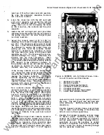
When the X relay or contactor is energized, it
closes its contacts.
One of these (X1-2) seals
in the X coil. The other three sets of contacts,
which are arranged in series, activate the closing
solenoid.
The breaker control scheme has an anti
pump feature which allows only one closure of
the breaker for a single operation of the closing
switch no matter how long the switch may be
held closed. This prevents the repeated operations
that would ensue
if
one of the automatic trip
devices was activated at the time of closing. The
Y
relay, together with the cut-off switch, provides
the anti-pump feature. The mechanical action of
closing operates the cut-off switch, reversing
the position of the contacts from that shown on
the diagram.
This energizes the
Y
relay,
if
contact is still maintained at the closing switch,
with the result that the X relay circuit is opened
by
Y
contacts
5-6.
This prevents the X relay
from again becoming energized.
Y
contact 1-2
seals in the
Y
coil as long as contact is main
tained at the closing switch.
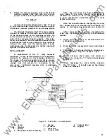
Electrically operated breakers may also be
closed by means of the maintenance handle which
is furnished with the breaker. This is a separate
tool and is simply a lever which permits an
operator to push upwards on the closing solenoid
armature. Two small hooks on one end of main
tenance handle are engaged in slots (9A) Figure 5,
located in the lower portion of the front escutcheon
(SA) Figure
5.
Rotation of the long end of the
handle downwards forces the shorter end of the
handle upwards against the bottom of the solenoid
armature, and closes the breaker.
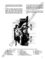
The breaker may be tripped open by any one
of a number of electrical tripping devices which
will be described in detail later in these instruc
tions.
An individual breaker may have none or
any combination of these devices. They are the
overcurrent tripping device, shunt tripping device,
undervoltage tripping device, reverse current trip
ping device, and open fuse lockout device. All
of them effect tripping by displacing the trip latch
of the mechanism.
The trip latch is rigidly
attached to a trip shaft which runs through the
breaker from left to right. Whenever the trip
shaft is rotated in a counterclockwise direction
looking from the right, the latch is displaced.
The tripping devices are all equipped with strikers
or trip arms which act against trip paddles rigidly
fastened to the trip shaft, causing it to rotate
on its bearings in a direction to trip the breaker.
The reverse current device and the shunt
tripping device each have a set of auxiliary switch
"a" contacts in their circuits. (An "a" contact
is open when the breaker contacts are open.)
This prevents their operation unless the breaker
is closed.
The undervoltage device coil is normally
continually energized. When the control voltage is
low or non-existent, as when the breaker has been
pulled out for inspection or maintenance, the
breaker is rendered trip-free by the undervoltage
device.
If
it is desired to close the breaker,
the device armature must be tied down or blocked
closed against the magnet. The open fuse lockout
device is used on all AKU breakers and breaker
fuse combinations.
The purpose of this device
is to trip the breaker upon the blowing of any
one of the breaker fuses.
MANUAL OPERATION
The manually operated breaker is closed by
first rotating the handle in a counterclockwise
direction through 90 degrees, then rotating it
clockwise back to its normal vertical position.
The counterclockwise stroke resets the mechanism,
readying it for the clockwise closing stroke.
The breaker may be tripped manually by
pushing the manual trip button. This action pushes
These instructions do not purport to cover all details or variat1ons in equipment nor to provide for every possible
contingency to be met in connection with installation, operation or maintenance. Should further information be desired
or should particular problems arise which are not covered sufficiently for the purchaser's purposes, the maHer should
be referred to the General Electric Company.
3
www
. ElectricalPartManuals
. com


